The first thing you need to know is how a car’s brake system works.
The Drum Brake System
A drum system uses hydraulic pressure to press the brake shoes against a brake drum to slow down the speed of the vehicle.
Here is what happens when you press the brake pedal.
The piston in the master cylinder sends pressure thru the brake lines to the wheel cylinders inside the brake drums.
The friction caused by the shoe pressing against the drum is stopping the wheel from turning
This slows the rotation of the wheels. A wheel cylinder contains pistons that use hydraulic pressure from the master cylinder to force the brake shoes against the brake drum.
The Disk Brake System.
The disk brake system uses hydraulic pressure to press a pad against the rotor.
Here is what happens when you press the brake pedal.
The piston in the master cylinder is activated and sends pressure thru the brake lines to the calipers and when the pad makes contact with the rotor, friction is created and this stops the wheel from turning.
This pad is held by the caliper, which fits over and around the rotor.
The braking system has to have brake fluid. The master cylinder reservoir stores the fluid and the master cylinder distributes the brake fluid under pressure, to the entire braking system of your vehicle.
The description above gives you the knowledge of how two different car brake systems work. These are some of the first things you need to know when troubleshooting and looking to fix any problems on your vehicle’s braking system.
Leatherneck wrote:Master Cylinder info by by: Dean Oshiro, Hot Rods USA
We got these with the permission of publishers long reads but well worth it. MC may look different but the purpose and inner workings are the same.
Master Cylinders: The basic design of master cylinders are single reservoirs or dual reservoirs. Before disc brakes all master cylinders had single reservoir. This was because you wanted to apply equal pressure to all 4 drum brakes. The proportioning between the front and rear brakes was regulated by the size of the wheel cylinders. Generally you ran bigger wheel cylinders in front, because it applied more pressure and if you need fine tuning you added a manual proportioning valve to the system. In the late 60's and 70's when disc brakes were being used more and more, there was a need to have a dual master cylinder, because the requirements were different when you ran disc brakes in front and drums in the rear. Remember the volume requirements of the OEM caliper? Well this high volume and more pressure required the factories to build the master cylinders so it was cheap to produce, have a large volume and met the requirements of both the disc and drum brakes. Notice the larger reservoir in the front portion of the disc/drum master cylinder and the small reservoir for the drum brakes.
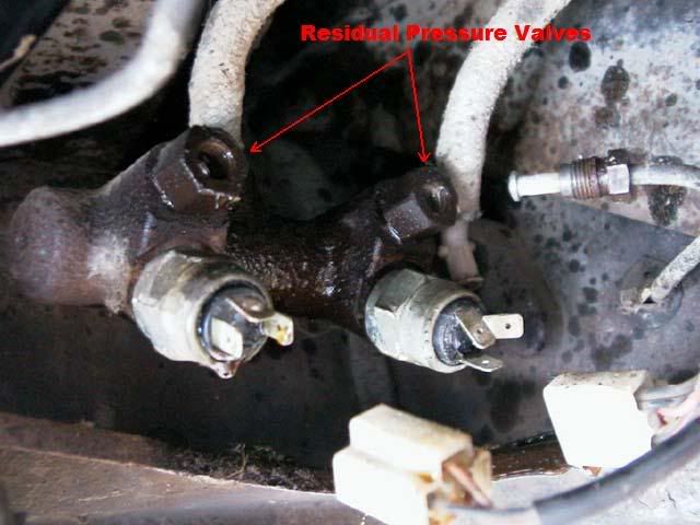
OEM single master cylinders are generally for drum brake applications. The earlier master cylinder had built in residual valves for the drum brake systems. This valve is needed so that the cup seals in the wheel cylinder has pressure against it preventing them from leaking. It also allows for a certain amount of pre-load on the mechanical parts. You can not use this master cylinder with built in residual valve(s) if you have disc brakes in front because of the residual valve. I have answered many questions regarding people that have installed brakes incorrectly by using a drum brake master cylinder.
If you experience a brake lock up after a few applications of the brake pedal, it is directly related to a residual valve retaining the brake fluid within the lines and not allowing the fluid to flow back to the master cylinder. The problem is either the wrong residual valve being used, a drum brake master cylinder being used on disc brake calipers, a inline residual valve plumbed in to the brake system with a built in residual valve in the master cylinder or a defective residual valve.
Most OEM tandem master cylinders will have a residual valve built in when there is a drum brake application. That is why it is important to buy the correct master cylinder based to application. Yes, you can remove the residual valve from the master cylinder, but often the reservoir is to small and it does not hold enough brake fluid for the disc brake application. So great care must be taking when using a modified master cylinder. OEM tandem master cylinders were designed to be cheap. Careful consideration should be made when selecting the master cylinder, because of the high volume of brake fluid required and pressure for the disc brake application. OEM tandem master cylinders do not produce the same volume as two side by side master cylinders. Remember the application is stacked one in front of each other so you have a limited travel and volume to work with.
For over 30 years race cars have used dual master cylinders, this is the use of two master cylinders that are side by side being applied at the same time. The mounting is generally done on the fire wall, but special applications have made it possible to mount these on the floor, under the dash or in a remote location. A balance bar is used to balance the force to each master cylinder. Think of a bar with a pivot point in the middle, when pressure is applied to the pivot point both ends move the same distance. Now think of the same bar with the pivot point move more to one side, when pressure is applied the shorter end will move before the long end. That is basically how the balance bar works. In a race car there is a cable connected to one end of the balance bar, this cable would go to a knob in the drivers compartment, so he can make adjustments as the condition of his brakes and road condition changes. The balance bar also eliminatesthe need for a proportional valve. On certain applications a remote reservoir(s) are used, in these applications it deletes the use of residual valves on disc brake applications. Master cylinders of this type do not have built in residual valves in them so if you have a drum brake application you will still need an inline ten pound residual valve, this is needed to retain pressure against the cups of the wheel cylinders.
There are major advantages to using dual master cylinders:
(1) Smaller diameter master cylinders can be used to increase output pressure. The design allows the application of two master cylinders being applied at the same, thereby doubling the volume output. Because of this high pressure output you will not need a vacuum booster. If you are running any type of camshaft, chances are you do not have enough vacuum to run the booster anyway. (2) The balance bar eliminates the use of a proportional valve and gives you the optional remote adjustment. (3) The remote fill applications deletes the need for residual valve normally used when the reservoirs are lower than the calipers.
When calculating the output pressure of each master cylinder you can not say that applied pressure is “shared” equally between the two (2) master cylinders. If the two master cylinders did not have a balance bar between them and the application of force was always equally distributed this statement would be true. The balance bar allows the applied pressure to be distributed unequally.
Example:
6:1 ratio pedal assembly
¾" master cylinders
Applied force of 100 pounds with your foot
The formula shows that this combination produces 1359 psi, however if you apply the 100 pounds of force to both of them equally it will only produce 50 percent or 679.5 psi.
What the balance bar allows you to do is apply 65% of the force to the front and 35% to the rear so the actual output pressures would be 883 & 475 psi.
This is how you are able to obtain maximum braking with the same amount of applied force. When you are using a tandem master cylinder (OEM type inline bore) the output pressure is equal in both ports and the only way to reduce the pressure to the rear braking system is through metering (distribution block, combination valve or engineering in the master cylinder) or proportional valve. This works fine when you have more than enough pressure with a power booster but when you are using a manual master cylinder this energy is “wasted”.
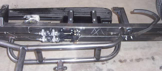
Here is a picture of the master cylinder mounting in one of my chassis I built. We have taken the 30 year old technology of dual master cylinders and applied it to this chassis. We used two 3/4 master cylinders with an out put pressure of 1359 psi each. This special mounting bracket mounts the master cylinders one on top of the other taking only 2.5 inches of width along the frame. The balance bar system allows full adjustment of the pressure balance and the remote fill eliminates the residual valves. This space saving feature provides additional room for your exhaust system. The deletion of the power booster also eliminates the need for vacuum.
Leatherneck wrote:Rotors info by by: Dean Oshiro, Hot Rods USA
Rotors: Rotors come in various designs, but basically there is a vented rotors and solid rotors. Rotors can be a one piece design with the hat or hub incorporated in the casting or the two piece design where the rotor is separate from the hat or hub. In this case the bigger the rotor the better. The bigger the diameter means it takes that much longer before the pad is in the same area during the rotation of the rotor. This size also gives a mechanical leverage "advantage" when you increase the diameter of the rotor with the same calipers and master cylinder.
A good example of upgrading would be if you have a Mustang/Pinto 9" rotor and upgrade to a 11" rotor. Not only does it allow more surface for cooling, it give a significant mechanical advantage. This results in less pressure and brake force by the caliper to stop your vehicle.
On vented rotors the fins should be far enough apart to allow air to flow between the fins, but close enough together so it allows enough support for the rotor walls. There can be as much as six tons of force being applied during braking and you do not want any deflection. Some vented rotors have curved fins to allow better flow of air and maximizing the transfer of heat. Don't forget these rotors can get up to 1,200 degrees F. so anything you can do to assist the transfer of heat is a plus. If you have ever watched a NASCAR short track race with the camera on the rotors, you will know how hot they get.
Solid rotors should never be used on a car weighing over 2,500 pounds. These were designed for light duty and never used on a vehicle where heavy braking is needed. These rotors serve a specific need and work very good under limited conditions.
Your better designed brake systems will have the rotor separate from the hat or hub. This allows the rotor to have a uniform temperature across the rotor (remember the NASCAR rotor?). By having this uniformity it minimizes the warping and cracking. Wilwood for an example uses an aluminum hub in the front which the rotors bolt to. This allows the hot rotor to cool at the same rate throughout the rotor, because it is made of different material and it is a separate part. The aluminum hub is also designed to displace heat and keep it away from the bearings (remember the modulus of elasticity number is 75 percent that of cast iron, meaning it will displace heat at a faster rate). Having a two piece design also prevents the storage of this heat compared to a one piece cast iron rotor. Calipers also benefit by having less heat transferred to them and it assists to keep the brake fluid under the boiling temperature.
Factories and cheaper brake kits use the one piece design, incorporating the hub/hat with the rotor, this was done strictly for cost. Notice that the hub and rotor is cast as one piece. This does not allow for the uniform distribution of heat and it is highly prone to warping and cracking due to the differences in temperature between the rotor and hub area. The one piece cast iron rotor will also retain heat longer, thereby transferring excessive heat to the calipers and brake fluid. The only advantage to the one piece design is initial cost. Did you really save any money? You would never see a one (1) piece rotor on a race car.
It would take pages to explain the relationship the rotor diameter has on the braking force. To make things as simple as I can it basically is the relation of the old rotor size vs the new rotor size.
Example: No change in tire size, going from a 11” rotor to 13” rotor. The effective radius of the 11” with a 2” pad would be 9” and the 13” rotor with the same pad width would be 11”. Or 11 ¸ 9 = 1.22 or 22% more efficient.
How Do I Diagnose Brake ProblemsLeatherneck wrote:Caliper info by Dean Oshiro , Hot Rods USA
There are several criteria which are vitally important when choosing, designing and working with a disc brake system: (1) Keep deflection down; (2) The use of hard linings to avoid flex from sponginess; (3) The use of small diameter flex lines; (4) The use of steel brake lines whenever possible; (5) Volume requirements of the caliper; (6) Available pedal ratio; (7) Master Cylinder size and design.
Calipers: There are two types of calipers floating or non-floating. Calipers are generally made from three common casting metals: magnesium, aluminum and cast iron. Calipers are made of different materials the most common are aluminum and cast iron. The material used in the calipers becomes important to help eliminate deflection, deflection results in a spongy pedal. The modulus of elasticity is very important to eliminate the deflection (flexing) of the caliper. The higher the modulus of elasticity number, the greater resistance to flex. Magnesium has a modulus of 6.5 million, aluminum has a modulus of 10 million, cast iron has a modulus of 14.5 million and steel has a modulus of 30 million.
The floating design was designed by the car manufacturers essentially to make the caliper less expensive to produce. It successfully applies the physics principle of "for every action caused an opposite and equal reaction happens." With this in mind they eliminated the piston(s) on one side of the caliper. This floating caliper is not solidly mounted, but slides back and forth on bushings or pins. When braking force is applied, the piston push the brake pad on the primary side and the reaction is the rotor being squeezed from the force of the pad primary side allowing the horseshoe shaped caliper to slide on the bushings so the secondary pads is used to squeeze the rotor. The caliper has to be very rigid retain low deflection or the principle will be lost. Cast iron and steel is used because of its' modulus number of 14.5 million and 30 million respectfully. This also increases the "sprung weight" and it retains the heat longer. The big advantage to the full floating design (single piston) is if the rotor has a slight run out (wobble), the floating feature will compensate without creating any instability. The other advantage is the single piston design is easier to bleed. The disadvantages are it heavier, retains heat, requires approximately 100 pounds of pressure more to "slide" the caliper and requires more volume of brake fluid due to the diameter of the piston. Floating designed calipers also come with 2 pistons on the same side.The two small pistons are placed in the leading edge of the caliper. If you will calculate the "area" of the two small pistons they equal the "area" of the larger piston. Spreading the force over a greater brake pad area allows for even pad wear. Normally the leading edge of the pad would wear before the trailing edge. Great solution for track and street cars.
Non-floating (fixed) calipers (i.e. 2, 4 or 6 piston) require a fixed mounting bracket. Most race applications use this type of caliper, because they are generally are made of aluminum which displaces the heat faster and requires both less pressure and less volume to operate. . Calipers made of aluminum are also not subject to corrosion and rust, like the Corvette calipers in the 60’s. The fixed design allows all the piston to be applied at the same pressure, because the pressure is equalized when pressure is applied, thereby allowing the rotor to be squeezed by opposing forces (piston on each side). Aluminum will displace heat 1.5 to 3 times faster than the cast iron or steel calipers. This is important when the rotors heat up to 1100 to 1200 degrees in a race car. Don't forget brake fluid has a boiling point of 550 to 700 degrees F. We have come a long way for the old 1965 Corvette design calipers, current non-floating calipers are easily rebuilt and even have thermo barrier type pistons that reducing the transfer of heat from the rotors.
OEM (floating) vs 4 piston (non-floating): Most of the brake kit currently being sold is the single piston OEM type caliper. In order for the caliper to squeeze the rotor it has to use a floating design, otherwise it would only apply pressure from one side to the rotor. Because of this design you loose approximately 100 psi. 4 piston caliper squeeze from both sides and are fixed (don't float), so they (4 piston) do not require as much pressure. The single piston caliper also requires more volume to work. The area of a 2-3/4" single piston caliper is 5.93 sq inches VS the area of two (2) pistons on a 4 piston design of 3.53 square inches. (multiply by 2 piston to get the area because the other 2 piston are being apply at the same time to squeeze the rotor, unlike the one piston design) 5.93 si VS 3.53 big difference. Does the volume effect the braking? Yes, it has a great effect on the master cylinder volume that is required for all 4 wheels. This will mean you will have to use a larger diameter master cylinder to meet the requirements of the calipers. The larger the master cylinder is the lower the pressure output.
Six Piston Calipers: 10 years ago when I first wrote this article there were no 6 piston calipers commonly used on street vehicles. You can thank computers for the fast advancement of c n c machined parts. The six (6) piston caliper is about the greatest thing since disc brakes itself. Generally there are four (4) smaller pistons and two (2) larger pistons. The two different size pistons allow the caliper to work at different levels without having as all the pistons operating at the same time. When you only need a little braking the 4 smaller pistons do the work, when you need to really stop the bigger pistons are activated. Great solution for street cars.
Brake bleeding without pumping?
No Brakes
Master cylinder problem?
Brakes---Pulling to the left
Travel of master cylinder piston
Brake Fluid Wet and Dry Boiling Points
broken brakes.. still
Hard Brake Pedal
Backing Plates
Spongy pedal after bleeding brakes
Parking brake arm clip
36mm axle nuts stuck...
hand brake
Disk Brake Rotors, Slots, Holes, Zinc Plating, Painting
Leaky brake line
Upgrade front drum to disc brakes
Master cylinder
rear break problem
brake line/ fuel line the same?
Brake Fluid Leak
Type 3 brakes for my 67 VW BUG!
Brake Adjustment
wheel studs
I need pedal assembly/brake pedal help type 1 1970 bug
Too much brake pedal play
Pedal Repair
Brakes question
Brake Lites 74 Beetle
OK to adjust brake to slightly touch drum?
brake master cylinder question
Braking Chug
Brakes....pedal hard then soft???
im putting discs all around my bug what master should i use?
I edited the quoted posts below to be generic.
ratwell wrote: I've written a lot here because once you get started and make one change you may not be able to stop because all of the parts are interconnected and the problem will just move someplace else.
First, the REAR brakes:
- First back off the parking brake adjustment all the way on both wheels.
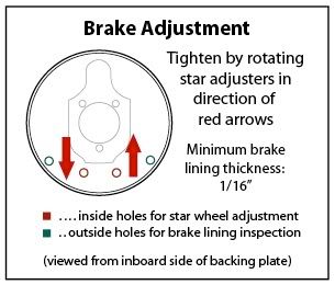
- Loosen the adjustment screws on the rear and remove the drums. Turning the stars clockwise engages the shoe so go the other way.
- The drum may not want to come off because it may be rusted to the hub in the center. Look at a picture of a drum removed and you can see where it will seize: the inner circle. Use penetrating oil, let it setup and give the drum a few whacks with a dead blow hammer.
- Inspect the drums looking for out of round. You may want to get them turned. Second, what condition are the shoes in? New shoes have about 5mm of brake material. Do they need replacing? Is either rear wheel cylinder leaking and in need of replacement? Everything is easy up to this point.
- Do the flex lines going from the brake lines to the wheel cylinder have the original DOT tag on them? If so they are original then the rubber is beyond end of life and they need to be replaced because they won't let to brakes release. You'll need an 11mm wrench and a crescent wrench or buy two 11mm flare nut wrenches for brake lines.
- There is some hardware in the brake drum like springs and such that need periodic replacement. Might as well replace it all while, you are in there.
- Before reassembly of the rears you want to use anti-seize compound in the barrels and on the threads of the adjustment screws so you won't have difficulty adjusting them in future. They do seize without it.
- Check the parking brake cable. Do you need a new one? They typically last a very long time.
- Adjust the rear brakes using the adjustment screws. Turn them each a little until the drum drags on the shoes and back off slightly. You always want a little drag so the brakes engage right away. I should point out that connecting the rear brakes is a proportioning valve.
How to identify correct brake components
Marc wrote:FRONT:
`58-`64 are identical.
`65 is still kingpin but has wider slots in the wheel cylinders and adjuster screws, and the adjuster ends of the shoes are angled.
`66/`67 are the same as `65 except for the backing plates (balljoint).
`68-up are still the same brakes but have adjuster access holes in the balljoint backing plates.
You can use the `65-up front wheel cylinders, shoes, and adjusters on any `58-up. Be sure that you have the wide/angled-slot adjuster screws to match the angled-end shoes.
REAR:
Pretty much the same as front, except that the major change in backing plates happened in `68 when the shoes got wider and the wheels cylinder bores smaller (from 19.05 down to 17.46mm).
M/C:
`58-`64 are all 19.05mm single-circuit
`65/`66 are 17.46mm single-circuit (often service-replaced by the 19.05)
`67 was 19.05mm dual-circuit with small feeder lines and is obsolete. It and all other variants of the early dual-circuit Type I M/C are now serviced with 113 611 015BD (also 19.05mm).
Karmann-Ghias and Euro-spec Beetles had a few differences, the above applies to US-market Beetles.
JonF wrote:There is no reason you shouldnt be able to handle rebuilding drum brakes yourself. there is not a lot to them. 4 springs 2 adjusters 1 wheel cylinder and 2 brake shoes per wheel
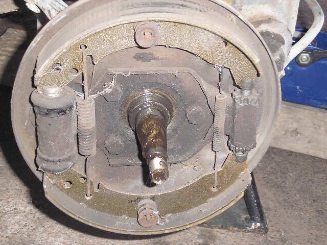
Al Von wrote:Yes! Great view, now I know at least what I'm grabbing for when I change the rear hoses.andk5591 wrote:There is a brass T on the drivers side - is this what you are looking for?
Thanks
Al Von

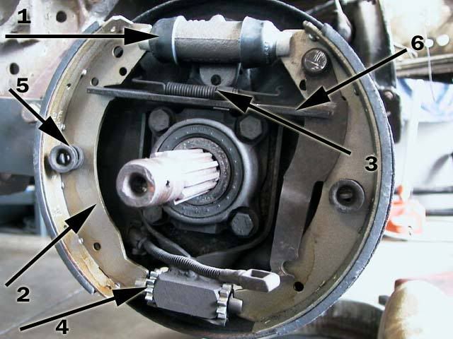
Kenny2428 wrote:I found this:
1. Wheel cylinder
2. Brake shoe
3. Upper return spring
4. Adjuster screws, or "stars" as some people call them
5. Shoe retaining springs, clips and cups
6. Connecting link.
This picture, however is of a rear brake drum. Everything is basically the same on the front, with the exception of the cable and lever for the parking brake.
FireBug1966 wrote:I just want to confirm this install.
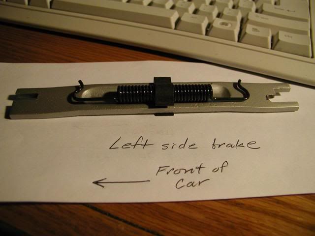
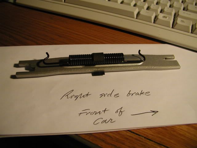
First of all, the same piece is sold for both the left and right side. There is no distinction between a left and right push bar.
And clearly the important thing is that the stepped notch goes to the back brake shoe. Right?
And what you end up with is this: On the left side the return spring sits in the "bowl" on the bar.
And on the right side the return spring ends up sitting on top of the "bump" on the bar.
What confuses is me is that on the left side the spring fits nicely in the "bowl". But on the right side it sits on top of the "bump" and well...it just doesn't seem right....although it is correct. Right?
56ovalbug wrote:According to CIP1, it fits both left & right.
http://www2.cip1.com/ProductDetails.asp ... %2D631%2DA
Disk Brakes

vw (o\!/o) nut wrote:vw (o\!/o) nut wrote:Dan,
We experienced the same issue with our mid-engine build.
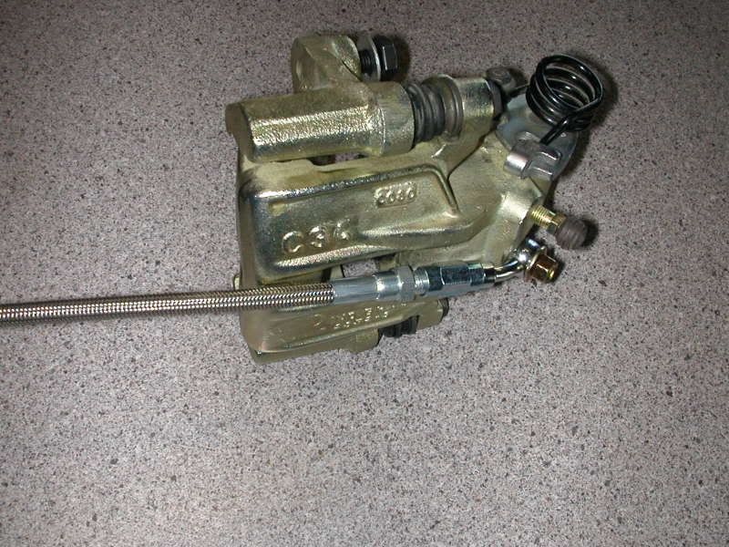
We eliminated the sharp bend by using a banjo fitting.
If you're interested in the details, let us know, and we'll post some pix.I'm almost certain that the same caliper is used on either swing or IRS.dan macmillan wrote: Please post what you used and part numbers if possible.
So here's the way we made it work.
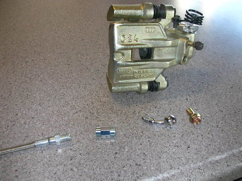
As you can see, the only parts that you will need are...
a banjo fitting - drag specialties 35degree # DS098150 (these are available in various angles)
(those motorcycle dudes have lots of kewl tidbits).
a brake hose bolt - dorman # 13940 (late model GM, avilable at your FLAPS)
and also an 3/16" / 10mm adaptor - edelman # 276000 (again, your FLAPS)
And this is the end result
If you have any ?s, let me know.
Neil
dan macmillan wrote:cooperhilscher wrote:Wow, that looks good, how big of a problem can that bend be? I am having serious problems with my rear disk brake kit... How do you adjust the pads? when I put them on the rotor they are wayyyy too tight and it just scrapes... I dont understand how they physically back off the rotor when you take your foot off the pedal, theres no springs or anything...
The bend can be very serious. It is needed to alow the flex hose to move as the pads wear and the caliper slides. if too tight then the fluid is trapped and the brakes will either not apply or not release.
Are they scraping with the pads removed?
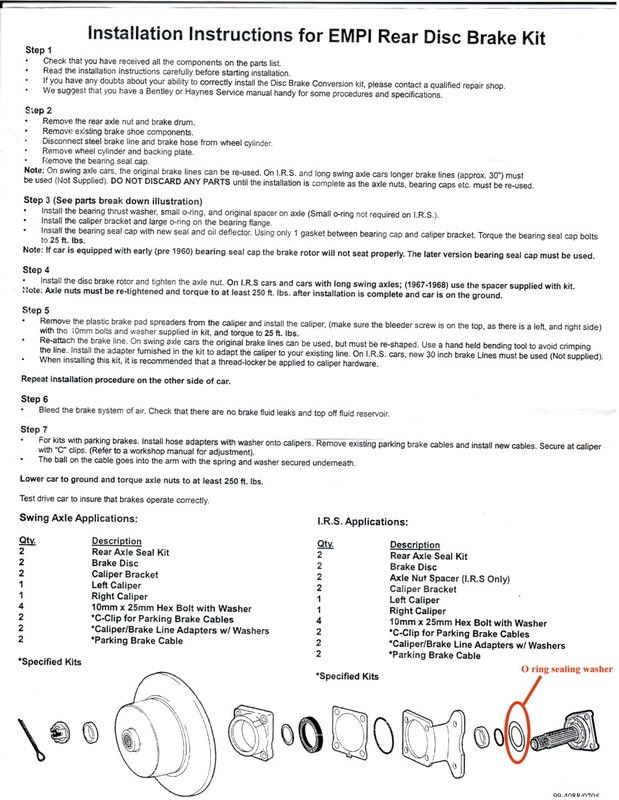
The kit comes with a thin washer that goes on first. I will call it the O ring sealing washer/bearing thrust washer.
If you fail to remove the old one and just add the new one it will set the rotor out too far and the rotor will hit the caliper support bracket.
I recommend just to reuse the original washer as it is better quality than the one supplied with the kit. Also make sure the spring on the top of the pads is not jammed in the slot in the caliper.
As for adjusting the pads and what retracts them.
The pads are self adjusting. Each time you press the pedal they contact the rotor. The retraction is accomplished by two things. Firstly no rotor is 100% true. The runout actually hits the pads and taps them back. The other is the square cut seal inside the caliper deforms on brake application and when released pulls the piston back in. For sake of argument the pads are always in contact with the rotor there is just no pressure applied
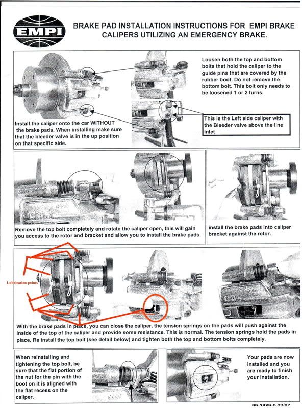
The pads and calipers should also be lubricated with a product such as neverseize at the points indicated. DO NOT LUBRICATE THE BRAKING SURFACE OF THE PAD WITH NEVERSIEZE.
There is another product that is used on the pad and rotor surface called Brake-in made by Kleen flo
but this should only be used on problen squeals
By the nature of the way disk brakes are designed...they squeal. This is a result of vibrations set up by the fact that the pads are perpendicular to the rotor surface. To combat this all metal to metal contact points should be lubricated. This also extends the life and performance of your brakes.
I have tried many kinds of brake lubricants and find that neversieze lasts the longest.
Where the pads contact the caliper supports, where the springs contact the calipers and inside where the caliper slide pins ride need lubrication.
LUBRICATION POINTS
A product such as
should be applied to the backs of the pads, the steel side. It is used to help control brake squeeling.Also make sure that the steel backing of the pad does not contact the rotor. Yes they can be installed backwards. I have seen it done and it is an expensive mistake. DO NOT APPLY TO THE BRAKING SURFACE OF THE PADS
Caution Do not expect to have 100% braking immediately. The pads must be bedded in. The glues and bonding agents in the pads are not fully cured and will be after the first few stops if not overheated.
Take the car out on a deserted road and drive at about 40 mph. Then every 100 yards or so, apply the brakes and slow it down to 20 mph, then slowly speed back up to 40 again. After doing that a handful of times, you can start to feel the pedal position and stopping power improving dramatically. TAKE YOUR TIME LET THEM COOL BEFORE THE NEXT STOP. And it never takes more than a few miles to completely break in new pads. If you hammer the brakes right from the stop the heat generated will ruin the pads and they will never stop right.
vw (o\!/o) nut wrote:My bad, Jeff. We've got some high-temp paint on the calipers now and...eastcoastconversions wrote: Neil,
How did you make this work? The brake hose is running towards the wheel if you set it up like this picture.
Jeff......
this is the proper mounting position.
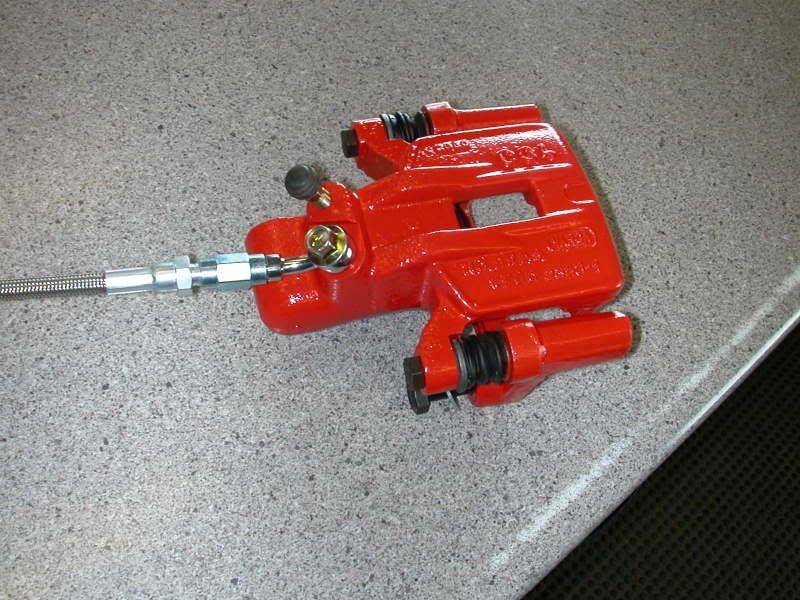
dune limo wrote:Here is a pic of a rear line from a VW caliper ---useing a hard line and a soft line seem's to be the proper way of doing it, putting a tight bend into a soft line is not gooddan macmillan wrote:I managed to post the stupid question of the day. There is no room to mount the caliper on the front side of the axle. The caliper must go on the back side of the axle. As for the bleeder reply. The bleeder does have to be at the top but this could have been accomplished by swapping calipers side to side. I am currently solving the problem pf having a sharp bend in the supplied short flex by making a short hard line coming off the caliper then adapting it to the short flex. The way the instructions from the kit have it the short flex has to be bent 175 degrees.Glasser wrote:I've never mounted disc's with e brake so not sure what to do with that but something that may be of concern is the bleeder valves for bleeding the system. If not at the highest point you may not get all the air out....... "may" is the key word. I should think that they should be mounted so as the bleeder is always on the top. Can the caliper be mounted in both locations with the bleeder on the top? If yes no worries your back to your original question. If no then this helps you make your decision on how they be installed.
I will post a pic when it is done.
Master Cylinders
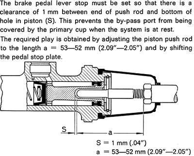
KTPhil wrote:Some masters (though I think it may only be the later dual masters) require a metal washer under that rubber "stopper." Otherwise the port gets blocked and it won't work or bleed right. Did your old master have one?
See #21 here (click to enlarge):
See #112 here (click to enlarge):
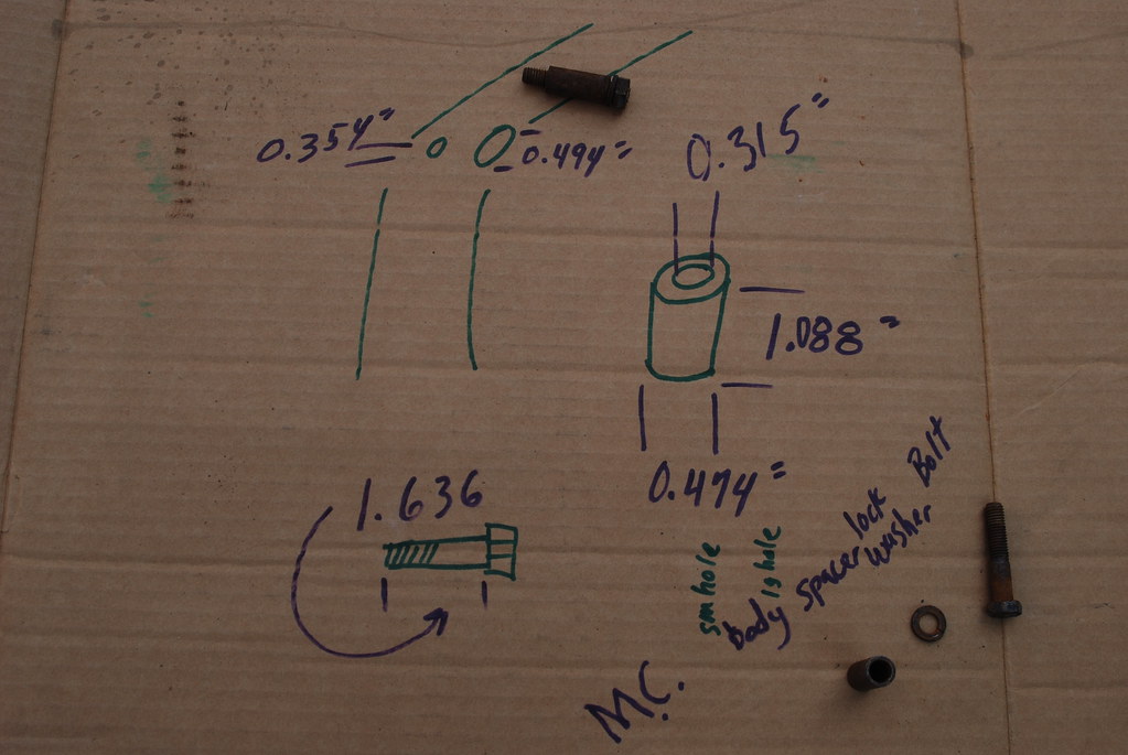
Framehead Spacer and Bolt DimensionsKTPhil wrote:
Brake Line Repairnice-diver wrote:
i only have an american caliper
the spacer pushes through the inside tin and buts up to the front tin. So it has to fit into the body on the inside.
Brake Warning LightMarc wrote:I've seen some lines that were patched using compression fittings but it's a big no-no. Changing the whole line is the way to go. Pull out the driver's seat and floormats and the rear seat cushion, study the shape of the old line and cut/rip it out. There's a few metal tabs holding it down alongside the tunnel, and rubber grommets at the front and rear bulkheads that you'll need to slice open to put over the new line and glue back together. The new lines usually come folded up in thirds or quarters, so you'll get some practice forming without kinking as you straighten it out; you may find that you can do it just fine with your bare hands (personally I tend to do more damage when I use a bender). Go easy and don't try to get every last ripple out. The shape of the line at the front is the most critical, you may even have a little excess to lose under the back seat with an extra bend or two. The trick in the rear is to loosen the bolt that holds the tee fitting to the LR frame horn until after you get the threads started on the new line, it'll make lining them up easier. Obviously, keep dirt out of the line/blow it out when done.
If it hadn't broken now, it probably would have the first time you did a panic stop with your new M/C so it's good to get it all done at once.
Interesting QuotesMarc wrote:The warning light is there to tell you that there is an imbalance in the pressure between the front & rear circuits of the brake system, nothing more!
If yours is an early `69 and hasn't had the mastercylinder replaced and the wiring modified, there will be three 2-prong switches on the M/C. The front & rear switches are in parallel and either one will make the brakelamps come on. On the early setup, the M/C has a special passage that connects the F & R sections of the M/C with an hourglass-shaped shuttle piston inside; if either circuit develops significantly more pressure than the other, the piston is displaced and tickles a probe that closes the third switch which lights the warning light.
On later cars (or those which have had the M/C replaced) you'll find two 3-prong switches instead; again either one will light the brakelamps, but they are double-throw switches that are ingeniously wired so that if one switch responds to brake fluid pressure and the other doesn't, the warning light on the dash will come on too.
If the light is coming on it could mean any of several things from grossly out-of-adjustment brakes to a bad M/C or a fluid leak (bad wheel cylinder for example) - or it could merely mean that one of the switches is bad.
Do as Jeff suggests and check your fluid level right away, but don't start replacing parts until you know what's really wrong.
BTW, on `72-up cars the push-to-test function of the warning light was replaced by an automatic proveout that lights the light briefly as you start the car.
Marc wrote:The early bus drums were wider but only slightly larger in diameter than Beetle drums. Late (`64-up) bus drums have larger-diameter axle splines, only the very-rare "`63½" bus drum will be large diameter with small splines.
Nothing cast into them that's a clue, like a part number that starts with 311 or 211? How about the diameter? The max diameter (for standard linings) on the bus drum is 9.901", on the III it's 9.822".
