Gas Gauge... again.
-
bradey bunch

- Posts: 189
- Joined: Tue Aug 04, 2009 9:13 pm
Gas Gauge... again.
Hi. I had an incorrect fuel gauge in my car. I got the correct one, for the '74 model year, but am having trouble hooking up the gauge correctley. On the sending unit, I have the gounded, solid brown wire on the chassis of the sender, and the brown with red stripe on the insulated connector. I am unsure how to hook it up. If someone could please take a picture of their 1974 gas gauge (the one with the brown trim ring, vibrator block on the back, and singular turn signal light) that would be superb.
-
vwbill
- Posts: 970
- Joined: Sat Feb 15, 2003 12:01 am
Re: Gas Gauge... again.
I think you're talking about the two types of fuel gauge setups? The new one you got doesn't have that extra brown thing on the back? I think Ray described the different setups. Have to do a search of the forum! I think you need to match the type of sender unit with the gauge... I haven't gotten to play with that yet on my car! Too affraid of the fuel and electrical thing since I bought a bug once that had a hole drilled in the tank and was wired to the radio and that hole with duct tape over it and I luckly pulled all the fuses but the ones needed just to drive her home when I picked her up!!
Sorry I can't help with this but the other guys are smarter with this stuff! Thank goodness we have Ray and the guys!! Thx, Bill,jr.
Sorry I can't help with this but the other guys are smarter with this stuff! Thank goodness we have Ray and the guys!! Thx, Bill,jr.
-
bradey bunch
- Posts: 189
- Joined: Tue Aug 04, 2009 9:13 pm
Re: Gas Gauge... again.
Thanks again Bill. The gauge is matched up with the sender properley, and I do have the block on the back. I have found many schematics for the 73 and earlier gauge and system, but no good diagrams for the 74. I have a detailed pic of an early gauge showing all the correct wire colors etc (it was easy because they were all snipped off with about 3 inches left on the gauge) but I need one for the later gauge. This is really pissing me off because its a problem the PO had, and I cant figure it out. If someone has a pic laying around (or can even make a detailed drawing..) that would be awesome!
Braden
Braden
-
vwbill
- Posts: 970
- Joined: Sat Feb 15, 2003 12:01 am
Re: Gas Gauge... again.
Hey Braden, did you look at the wiring diagram at http://www.vintagebus.com/ under 1974 412 page 2. the path is 37 and the gauge is labeled G1 and the sender is G. I have to use my Clymer book to get the english and easier view but use the color DE version to get the wiring colors... J6 is the voltage vibrator. Maybe you can get something from that? THx, Bill.jr
-
bradey bunch
- Posts: 189
- Joined: Tue Aug 04, 2009 9:13 pm
Re: Gas Gauge... again.
Thanks Bill. I have printed off that diagram, but it is hard (at least for me) for me to read where each wire goes actually on the sender, because on that diagram, they have "exploded" the gauge and shown all of the internal connections as well. Plus, all I have to go by are wire colors, because I am not too skillfull at tracing wires.
Braden
Braden
-
Bill K.

- Posts: 563
- Joined: Mon Oct 27, 2003 10:50 pm
Re: Gas Gauge... again.
Okay Braden, mind you I don't have a '74 or a '74 guage, but try this:
1. First, you HAVE to know how to use a multimeter. This site has some "for dummies" posts...
2. Use multimeter to find the 12V wire - red probably. This goes to the back of the clock. If your clock doesn't work see this -- http://www.aircooledtech.com/vdo_repair/
3. The clock won't work unless it is grounded. Be sure the resistance between the mounting screws an the "31" double lug on the back of the clock is about 0 ohms. You may need to scrape, scrub, and clean to get the crud off so a clean ground is made.
4. The ground wire must be connected to chassis ground. Use the multimeter to check the brown ground wire that is connected to double lug "31" is grounded - one probe on the wire end, the other touching bare chassis.
5. Now the gas... The 74 has the vibrator and two wires, just like super beetles. I'm not sure how to check the vibrator It sends pulses of 12V to the gauge for a smoother reading. If it's broke, the needle will bounce.
6. A different 12V wire (black probably) needs to go to the male connector on the vibrator. Find it with multimeter as in #2, but with the key on.
7. The vibrator is plugged into the back of the gauge - not sure what it is labeled on the gauge. You'll have the gauge pulled out of the dash with all the wires connected, right?
8. There should be a "G" terminal on the back of the gauge just like the -73's. This goes to the fuel sender and connects to the terminal with the insulated white base. The spare I have has a red/brown wire connected. Check the resistance from gauge end of wire to the sender end using multimeter (should be about zero ohms) with the key off. If the wire is disconnected or broken - empty always.
8. The fuel sender also has a ground (brown) wire that needs to be connected to chassis ground and verified like in #4.
9. The vibrator needs to be screwed to the back of the gauge and verified for ground also (vibrator housing to "31" lug). Bad grounds will peg the gauge full.
A picture of the back of your gauge could help us help you,
Bill
1. First, you HAVE to know how to use a multimeter. This site has some "for dummies" posts...
2. Use multimeter to find the 12V wire - red probably. This goes to the back of the clock. If your clock doesn't work see this -- http://www.aircooledtech.com/vdo_repair/
3. The clock won't work unless it is grounded. Be sure the resistance between the mounting screws an the "31" double lug on the back of the clock is about 0 ohms. You may need to scrape, scrub, and clean to get the crud off so a clean ground is made.
4. The ground wire must be connected to chassis ground. Use the multimeter to check the brown ground wire that is connected to double lug "31" is grounded - one probe on the wire end, the other touching bare chassis.
5. Now the gas... The 74 has the vibrator and two wires, just like super beetles. I'm not sure how to check the vibrator
6. A different 12V wire (black probably) needs to go to the male connector on the vibrator. Find it with multimeter as in #2, but with the key on.
7. The vibrator is plugged into the back of the gauge - not sure what it is labeled on the gauge. You'll have the gauge pulled out of the dash with all the wires connected, right?
8. There should be a "G" terminal on the back of the gauge just like the -73's. This goes to the fuel sender and connects to the terminal with the insulated white base. The spare I have has a red/brown wire connected. Check the resistance from gauge end of wire to the sender end using multimeter (should be about zero ohms) with the key off. If the wire is disconnected or broken - empty always.
8. The fuel sender also has a ground (brown) wire that needs to be connected to chassis ground and verified like in #4.
9. The vibrator needs to be screwed to the back of the gauge and verified for ground also (vibrator housing to "31" lug). Bad grounds will peg the gauge full.
A picture of the back of your gauge could help us help you,
Bill
-
vwbill
- Posts: 970
- Joined: Sat Feb 15, 2003 12:01 am
Re: Gas Gauge... again.
Hey, did you get the gauge working? Thanks for the parts payment too! Lot of great info from the guys to help! bill,jr.
-
bradey bunch
- Posts: 189
- Joined: Tue Aug 04, 2009 9:13 pm
Re: Gas Gauge... again.
Well yes, the fuel gauge itself is working, thanks for the help everyone. The alternator charging light is not working, however, and i know the bulb itself is good. when i turn the ignotion on, the oil, brake warning, and alt. light do not come on. all the lights themselves are good. is there something that points to this problem (a relay or something?). Also, i heard the alt. light must be working for the alternator to work. is this true? because my alternator is not charging. btw, I have the solid blue wire going to the alt. light as is shown by the diagrams I have seen.
-
david58

- Moderator
- Posts: 14101
- Joined: Sun Oct 23, 2005 6:14 pm
Re: Gas Gauge... again.
With the key on engine off, the ALT light will illuminate, because there is a ground to the circuit, because it is not charging, then when you crank it the light goes out because the ALT supplies power to the circuit, but only if it is charging. The bulb has to see a ground and power source to illuminate. Power to the bulb is supplied from the fuse panel, the ground comes either from the engine not running with the key on, or from a ALT or Gen that is not charging. Power on both sides of the bulb makes the bulb go out. This isn't a short circuit, it is how the system was designed to function.bradey bunch wrote:Well yes, the fuel gauge itself is working, thanks for the help everyone. The alternator charging light is not working, however, and i know the bulb itself is good. when i turn the ignotion on, the oil, brake warning, and alt. light do not come on. all the lights themselves are good. is there something that points to this problem (a relay or something?). Also, i heard the alt. light must be working for the alternator to work. is this true? because my alternator is not charging. btw, I have the solid blue wire going to the alt. light as is shown by the diagrams I have seen.
Hot, humid air is less dense than cooler, drier air. This can allow a golf ball to fly through the air with greater ease, as there won't be as much resistance on the ball.
-
bradey bunch
- Posts: 189
- Joined: Tue Aug 04, 2009 9:13 pm
Re: Gas Gauge... again.
Ok. So the fact that the light(s) are not coming on at all (even with ignition on and not running) means there is probably a bad ground, correct?
-
david58
- Moderator
- Posts: 14101
- Joined: Sun Oct 23, 2005 6:14 pm
Re: Gas Gauge... again.
It means the circuit is open a better word is dead.
1. Either there is no power to the bulb.
2. The bulb is bad.
3.Or the wiring from the ALT to the bulb is open.
Open means there is a break in the wiring that isn't making connection.
Let's test the circuit.
You will need a test light.
Hook the test light to B+ on the ALT and probe the blue wire. If the test light illuminates then the problem is further forward. Notice I didn't say to turn the key on. The Alt gets power at all times, and since it isn't charging the blue wire will be grounded. So this part of testing can be done with the key off or on. The preferred method would be with the key on so the circuit is live.
So while testing with the key on we should disconnect the wire going from the coil to the distributor, so we don't burn up the points or electronics in the distributor. This is the wire going to terminal #1 at the coil. The reason behind disconnecting terminal #1 as opposed to disconnecting terminal #15 is that terminal #15 IS NOT FUSED from the factory, so if this wire shorts out to ground there is a great chance you will fry the main wiring running thru the car.
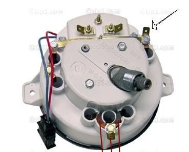
OK so since we are working with a ALT and it is internally regulated the blue wire goes straight to the bulb. So let's pop the bonnet open and do some more testing. Hook your test lamp to the ground bus bar to the left of the speedometer. It has several brown wires going to it. Now that wasn't too hard was it? OK now looking at the pic below probe anyone of the 3 points with with the red lines pointing to them the key on. If the test light illuminates the circuit is fine. If the bulb doesn't illuminate This would mean the bulb is no good or has a bad connection.
1. Either there is no power to the bulb.
2. The bulb is bad.
3.Or the wiring from the ALT to the bulb is open.
Open means there is a break in the wiring that isn't making connection.
Let's test the circuit.
You will need a test light.
Hook the test light to B+ on the ALT and probe the blue wire. If the test light illuminates then the problem is further forward. Notice I didn't say to turn the key on. The Alt gets power at all times, and since it isn't charging the blue wire will be grounded. So this part of testing can be done with the key off or on. The preferred method would be with the key on so the circuit is live.
So while testing with the key on we should disconnect the wire going from the coil to the distributor, so we don't burn up the points or electronics in the distributor. This is the wire going to terminal #1 at the coil. The reason behind disconnecting terminal #1 as opposed to disconnecting terminal #15 is that terminal #15 IS NOT FUSED from the factory, so if this wire shorts out to ground there is a great chance you will fry the main wiring running thru the car.
OK so since we are working with a ALT and it is internally regulated the blue wire goes straight to the bulb. So let's pop the bonnet open and do some more testing. Hook your test lamp to the ground bus bar to the left of the speedometer. It has several brown wires going to it. Now that wasn't too hard was it? OK now looking at the pic below probe anyone of the 3 points with with the red lines pointing to them the key on. If the test light illuminates the circuit is fine. If the bulb doesn't illuminate This would mean the bulb is no good or has a bad connection.
Hot, humid air is less dense than cooler, drier air. This can allow a golf ball to fly through the air with greater ease, as there won't be as much resistance on the ball.
-
MGVWfan

- Posts: 825
- Joined: Fri Jun 11, 2004 9:23 pm
Re: Gas Gauge... again.
Another quick check...do you have the little brake warning light thing in between the speedo and clock/warning lamp cluster? It uses the same alternator diode trio line the alternator warning lamp does (the blue wire). It should light up when the ignition switch is "on" and the engine's not running, along with the alternator warning lamp. If it's "on" and the alternator warning lamp's "off", the problem's in the alternator warning lamp, if the brake lamp's "off" also, the problem's wiring most likely.
-
david58
- Moderator
- Posts: 14101
- Joined: Sun Oct 23, 2005 6:14 pm
Re: Gas Gauge... again.
I just reread my 2:56 am post I left out one test.

OK so since we are working with a ALT and it is internally regulated the blue wire goes straight to the bulb. So let's pop the bonnet open and do some more testing. Hook your test lamp to the ground bus bar to the left of the speedometer. It has several brown wires going to it. Now that wasn't too hard was it? OK now looking at the pic below probe anyone of the 3 points with with the red lines pointing to them the key on. If the test light illuminates the power circuit is fine. Now hook the test lamp to the blue wire and probe the 3 points. If the test lamp doesn't illuminate there is a open in the blue wire between the alt and the speedo. If the test lamp lights then this would mean the bulb is no good or has a bad connection.
I should have said this but my eyes were bleeding.OK so since we are working with a ALT and it is internally regulated the blue wire goes straight to the bulb. So let's pop the bonnet open and do some more testing. Hook your test lamp to the ground bus bar to the left of the speedometer. It has several brown wires going to it. Now that wasn't too hard was it? OK now looking at the pic below probe anyone of the 3 points with with the red lines pointing to them the key on. If the test light illuminates the circuit is fine. If the bulb doesn't illuminate This would mean the bulb is no good or has a bad connection.
OK so since we are working with a ALT and it is internally regulated the blue wire goes straight to the bulb. So let's pop the bonnet open and do some more testing. Hook your test lamp to the ground bus bar to the left of the speedometer. It has several brown wires going to it. Now that wasn't too hard was it? OK now looking at the pic below probe anyone of the 3 points with with the red lines pointing to them the key on. If the test light illuminates the power circuit is fine. Now hook the test lamp to the blue wire and probe the 3 points. If the test lamp doesn't illuminate there is a open in the blue wire between the alt and the speedo. If the test lamp lights then this would mean the bulb is no good or has a bad connection.
Hot, humid air is less dense than cooler, drier air. This can allow a golf ball to fly through the air with greater ease, as there won't be as much resistance on the ball.
-
MGVWfan
- Posts: 825
- Joined: Fri Jun 11, 2004 9:23 pm
Re: Gas Gauge... again.
David58..is that you, Deathbus?
-
bradey bunch
- Posts: 189
- Joined: Tue Aug 04, 2009 9:13 pm
Re: Gas Gauge... again.
Wow thanks. As soon as I get some time I will be sure to do those tests, but I thought i might add that the brake light, the oil light, and the alt light are not illuminating with the ignition on but car not running, and I know MGVWfan said something about that. also, the wiring seems to be half '74 and half '73.