i have now collected my spare centrelink so some over the next few weeks will making a start on the rebuild.
Just need to find a source in the UK for the bronze washers
Is it possible to restart a cntrelink rebuild thread?
-
raygreenwood

- Posts: 11914
- Joined: Wed Jan 22, 2003 12:01 am
Most bearing shops that sell 0-rings and industrial ball abd roller bearings also sell "plane" bearings....and generic thrust washers. These are just generic bronze thrust washers.
In general....you need to buy whatever they have with a larger than you need OD and smaller than your pin....ID. Preferably not massively larger in either dimension.....because you will be sanding and grinding these to size.
Thicknesses around .050" to .070" will do fine.
Ray
In general....you need to buy whatever they have with a larger than you need OD and smaller than your pin....ID. Preferably not massively larger in either dimension.....because you will be sanding and grinding these to size.
Thicknesses around .050" to .070" will do fine.
Ray
-
herr_sparky
- Posts: 145
- Joined: Wed Oct 24, 2001 1:01 am
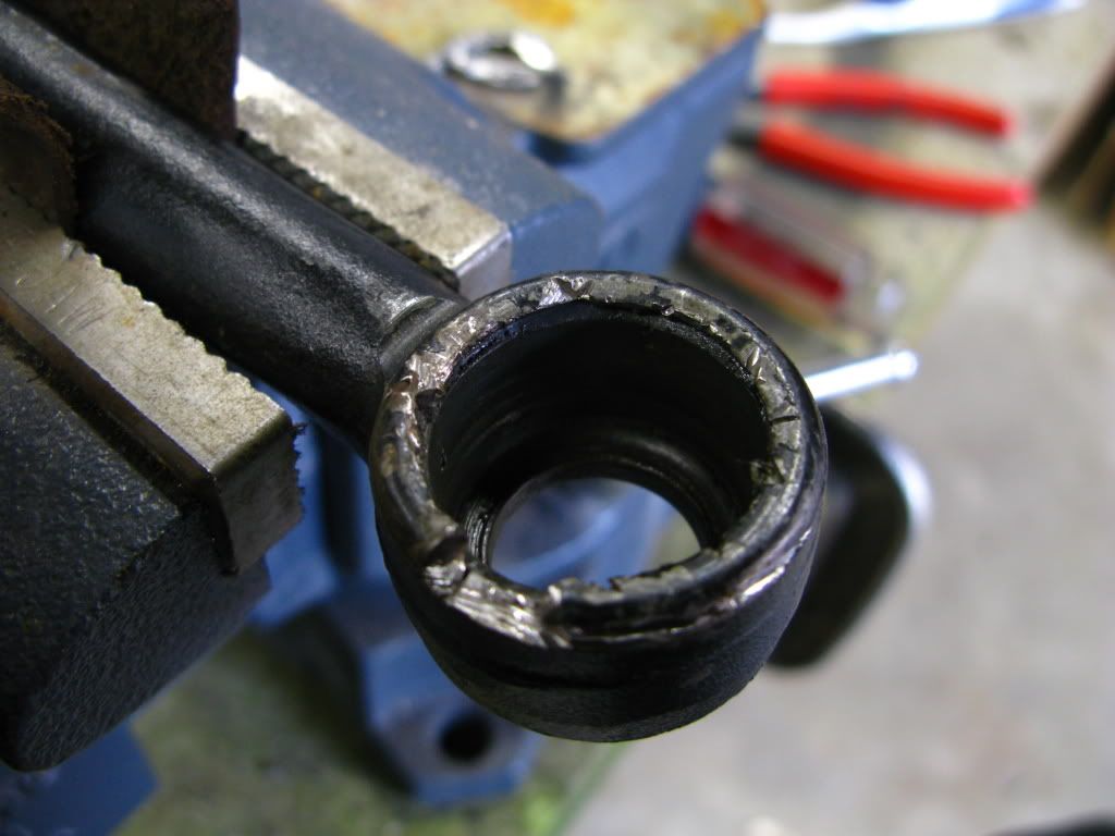
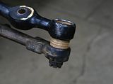
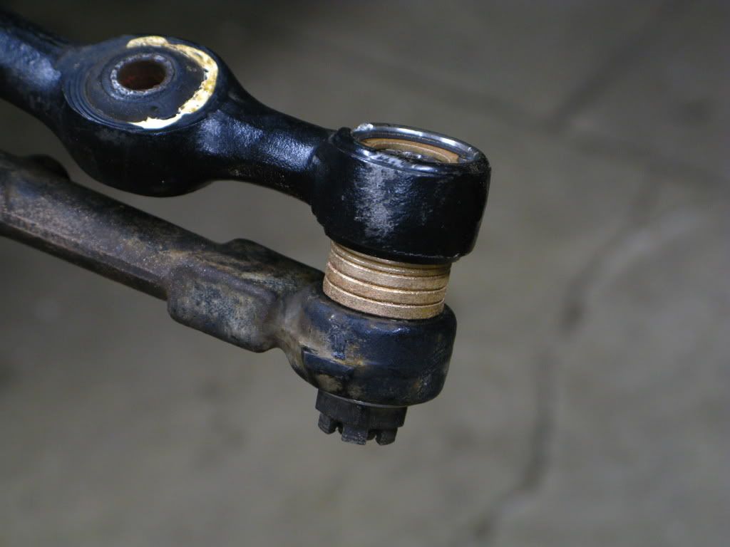
i just got one side of mine apart...what a heinous task...i misunderstood its construction and ended up totally massacring the outer, swaged (?) ring: (detail)
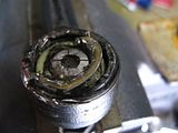

so let me make sure i'm getting this right:
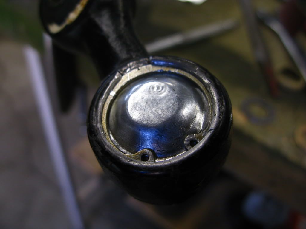
1. the nylon under the cap is replaced with an assortment of bronze bushings sized so that an internal snap ring can be fitted into the grove where the cap used to live, and the same is done to the other side, just enough to fill the inside and capture the pin tightly.
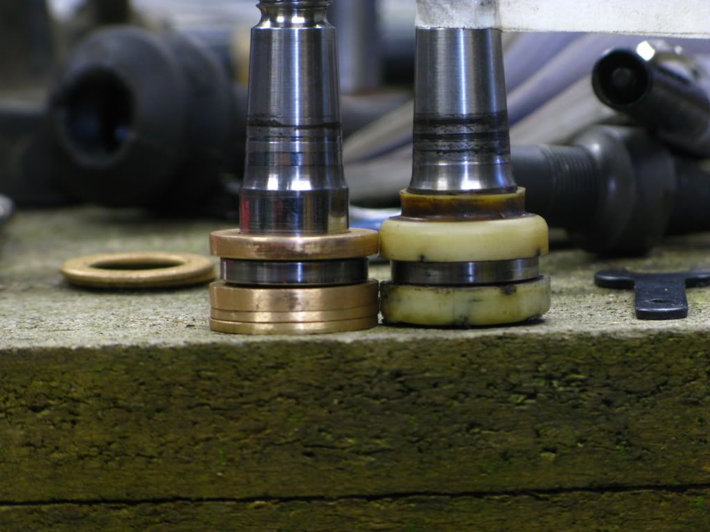
2. in the space between the outer faces of the 'link end and the arm, another assortment of washers...but this time they need to be of varying inner diameters to match the taper of the pin, right? thus:
so let me make sure i'm getting this right:
1. the nylon under the cap is replaced with an assortment of bronze bushings sized so that an internal snap ring can be fitted into the grove where the cap used to live, and the same is done to the other side, just enough to fill the inside and capture the pin tightly.
2. in the space between the outer faces of the 'link end and the arm, another assortment of washers...but this time they need to be of varying inner diameters to match the taper of the pin, right? thus:
ive checked out bill k.'s (killer) website and the other threads here, just looking for as much info as possible... most of the internal groove is intact on mine, but the ring took a heavy beating by the cutting wheel, i'm not sure if its still useable. good times!....you need to buy whatever they have with a larger than you need OD and smaller than your pin....ID. Preferably not massively larger in either dimension.....because you will be sanding and grinding these to size.
Thicknesses around .050" to .070" will do fine.
Ray
-
raygreenwood
- Posts: 11914
- Joined: Wed Jan 22, 2003 12:01 am
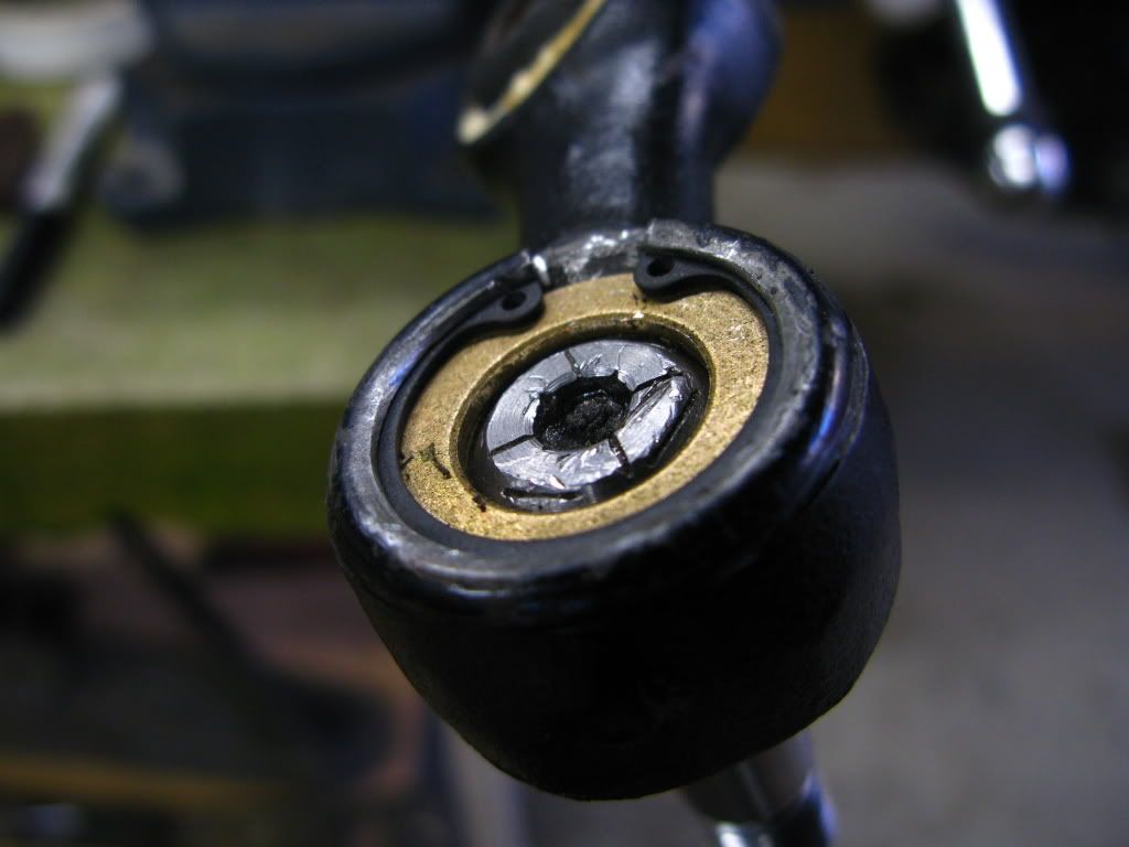
It "looks" like you should be OK. A lot of the original groove that captured the original cap.....is mashed down from the original swaging.
What you need to do...is get your vice or holder to mount teh link in....get your dremel with an assortment of the "thin" cut-off wheels...and some fiberglass cut-off wheels.
Warning...do NOT forget to use a dust mask with dremel cut-off wheels....especially the fiberglass wheels. I have done some catual documented damage to my lungs and nose in the past.
DO NOT breather the dust from the wheels.
Get one of those little square bricks about 3/8" square and 1" long that comes with dremel tools. That is for groinding against to reshape the outer diameter of various grinding tools like cut-off wheels.
Patiently....with a steady had...you want to enlarge teh groove where the original back cap was swaged into. You do not want much depth added...mainly a clean groove of adequate thickness for you snap ring. Do not cut through the groove or you are done.
Fear not....I screwed up the first one too...as I also did not quite understand how it was constructed.
For future reference...I cut a vertical slot at 12, 3, 6 and 9 o'clock. The na cross shaped slot on the dome....like you did. Some light prying at the slot from te hcertical slots witha very thin screwdriver and mallet...and then grip the pieces of the domw with vice grips and twist them out. Ray
-
herr_sparky
- Posts: 145
- Joined: Wed Oct 24, 2001 1:01 am
i finished one side...took about $60 in bronze and dremel parts and 3 days of slumping over the vice...and i'm not sure i'm pleased with the results. i had a perfectly tight, sealed joint before, now i have neither. i can see the benefit to replacing the external nylon sleeve (that fills the gap between the arm) but i have to say, i'm inclined to leave the insides alone next time...fabricating the cap alone took hours and its a loose, wandering fit (because its smaller than the circlip groove in order to fit past the opening)...
 *
*  *
*  *
*  * (detail)
 *
*  *
*  *
*  * (detail)
-
raygreenwood
- Posts: 11914
- Joined: Wed Jan 22, 2003 12:01 am
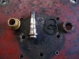
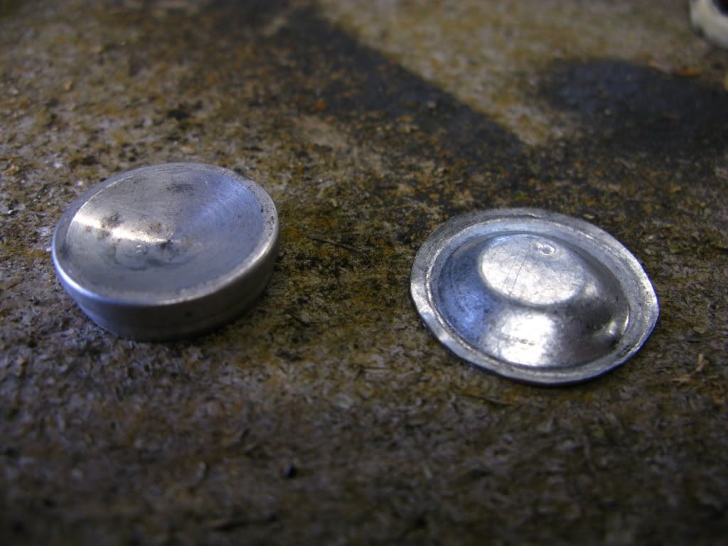
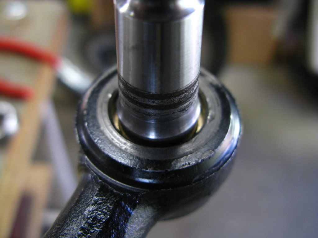
You are not done yet. The hole at the rear of the last thrust washer...is too large. It should be ok...but you should be able to find them smaller.
The metal rear dome cover looks fine. You should be able to simply put just a hair bit of silicone around that....good silicone...and it will never leak again.
Leaving the internal nylon in, is a worthless endeavor. It fails 100% of the time....100%.
It is a chemical issue. The material is 6/6 nylon...and is KNOWN in every industry it has been used in since the 1960's to fail in the prescence of ANY moisture. You just got to it early. If it were 6/12 nylon...it would be a different story.
Also, you should have slightly enlarged the opening in the top where the original bushing protruded through...and used a bronze journal collar and then trimmed to fit. That way you do not need that stack of washers.
I used a pair of modified rear master cylinder boots on mine and they worked very well.
Over all...it looks good except that you need to groove each washer so grease can flow around.
Dremel parts can be expensive...but how much did you spend on the bronze? Those thrust washers should be dirt cheap. I bought mine at ace hardward for less than .60 cents each. They are simple bushings and thrust washers made by Jandorf. Ace Hardware has boxes of them.
If the cap is a loose fit...get a thicker thrust washer and lap it down. They generally have a high variation in thickness. In the same bin...I find thrust washers that vary as much as .030" in thickness...but are the same size in ID and OD.
Why so long on the cap? Just asking. Mine took about 10 minutes.
Go to a hobby shop...where they sell scale tubing and sheet and balsawood for model building. They sell polished stainless strip...about 1" x 12" by .010"....for about $3
That thickness measurement...is the most critical. This back cap has no structural usage. Its just a dust cap.
I used an actual pair of sharp fiskars scissors to cut a disc that was about .050" too large in diameter. In other words....when flat...it lapped over onto the installed snap ring almost all the way from edge to edge.
Layed it over a washer on a flat piece of wood...and got a 13/16" socket and linded it up. Whacked it once. Got a domed lid. When you whack it over the washers...the edges pull in so its just the right size for the snap ring to cover.
Keeping the material thin....,010"....makes it easy to form. There will never be any load against this cap. Its just a cover.
Don't give up. You are almost there. Ray
-
herr_sparky
- Posts: 145
- Joined: Wed Oct 24, 2001 1:01 am
yeah, i'm still working on it, but mostly out of sheer morbid curiosity. i had to take a day off because my back hurts and we finally got a sunny day for a proper motorbike ride...
anyway, 60¢?! you sure it was an Ace Hardware, not Goodwill? mine cost $2.50 each, some of them were as low as $2.20, others $4 (like the flanged bearing i havent tried yet) and i went to a True Value chain...
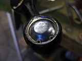
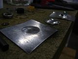
the material for the cap is made from a piece of tin flashing i found laying around (about 0.015"), and its so soft that all my attempts at using some kind of anvil/whatever just made it tear or pop right through. i cut out squares with tin snips and gradually trimmed it down to a rough circle. here you can see a couple early attempts in the background:
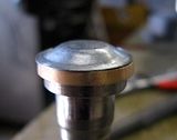
and the obscure bicycle suspension tool/part/somethingorother i used to shape the dome with a small ball-peen hammer:

the last step was shrinking it down on a belt sander and giving the final form by hammering it over the pin itself:

i noticed Bill K's rebuild used a sliver of the original nylon in this place, and i even bought some black nylon sleeve to try and shape my own with new materials...of course, a properly sized flange bearing would be best... the ones at the Worst Value that were the closest in size already (requiring less work) were an absurd $17!
i'm determined to make it work just to fulfill my own masochistic habits, but i'm still not sure i would do it this way again...regardless of the plentiful reasons to...i might change my mind if i can finally get a good result, though...
thanks for all the encouragement/instructions! more later...
anyway, 60¢?! you sure it was an Ace Hardware, not Goodwill? mine cost $2.50 each, some of them were as low as $2.20, others $4 (like the flanged bearing i havent tried yet) and i went to a True Value chain...
the material for the cap is made from a piece of tin flashing i found laying around (about 0.015"), and its so soft that all my attempts at using some kind of anvil/whatever just made it tear or pop right through. i cut out squares with tin snips and gradually trimmed it down to a rough circle. here you can see a couple early attempts in the background:

and the obscure bicycle suspension tool/part/somethingorother i used to shape the dome with a small ball-peen hammer:
the last step was shrinking it down on a belt sander and giving the final form by hammering it over the pin itself:

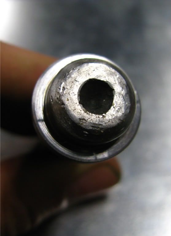
i can see that, now. the store had two IDs to choose from: 5/8" and 1/2", so i'll try the smaller one. from what i can tell, the pin needs more support at its extremities inside the cavity to keep it from rocking side to side, and i dont have that at the other end, either; in other words, the hole where the pin comes out and starts to taper...is void of any material:You are not done yet. The hole at the rear of the last thrust washer...is too large. It should be ok...but you should be able to find them smaller.
i noticed Bill K's rebuild used a sliver of the original nylon in this place, and i even bought some black nylon sleeve to try and shape my own with new materials...of course, a properly sized flange bearing would be best... the ones at the Worst Value that were the closest in size already (requiring less work) were an absurd $17!
i'm determined to make it work just to fulfill my own masochistic habits, but i'm still not sure i would do it this way again...regardless of the plentiful reasons to...i might change my mind if i can finally get a good result, though...
thanks for all the encouragement/instructions! more later...
-
herr_sparky
- Posts: 145
- Joined: Wed Oct 24, 2001 1:01 am
-
raygreenwood
- Posts: 11914
- Joined: Wed Jan 22, 2003 12:01 am
Any kind of plastic will be bad. Part of the reason why this joint was weak...was beacuse the pin sticking out of it was so long and there is a lot leverage and side loading. Of course a bushing or stack of washers can take away a lot of that side loading....all it takes is normal steering and the plastic flexes. As they get older...it cracks. You caught yours before thsi stage. Most people do not.
Once it cracks, moisture can get into the plastic all over the place...and it literally turns to a powder.
As far as teh bronze thruts washers..even in Mcmaster Carr...they are between 98 cents and $1.56 each for the sizes we need. You are looking at a maximum of about $10 per side.
Yeah...sorry... some of teh local hardward stores get really stupid on their pricing for simplestuff like this.
Also.....the plastic part whose collar went up through the cup and was the kind of spacer that wrapped around the pin and spaced the joint from the idler and pitman arms.....and the stack of bronze washers you have..can all be taken care of with one piece of bronze.....and is called a flanged bronze bearing. Looks like a peice of tube with a flange or ledge at one end.
It takes a little sanding....but metric ones at Mcmaster carr on page 1120 are $1.32 to $1.72 each. Those end up taking away about 10-12 of those thrust washers you have.
This rebuild...is not just a replacement for stock...or a convenience that allows you to have a centerlink that can always be rebuilt. Thats all fabulous. But this link will be MUCH tighter...and MUCH better steering.
Bay the way...you are doing excellent work. It took me more than one attempt to figure out what was really needed and how tight everything needed to be and where it all needed support.
I rebuilt one for someone on the forum about two years ago. We should do a search and find out how everything is doing.
The cap on the back...looks great!Ray
Once it cracks, moisture can get into the plastic all over the place...and it literally turns to a powder.
As far as teh bronze thruts washers..even in Mcmaster Carr...they are between 98 cents and $1.56 each for the sizes we need. You are looking at a maximum of about $10 per side.
Yeah...sorry...
Also.....the plastic part whose collar went up through the cup and was the kind of spacer that wrapped around the pin and spaced the joint from the idler and pitman arms.....and the stack of bronze washers you have..can all be taken care of with one piece of bronze.....and is called a flanged bronze bearing. Looks like a peice of tube with a flange or ledge at one end.
It takes a little sanding....but metric ones at Mcmaster carr on page 1120 are $1.32 to $1.72 each. Those end up taking away about 10-12 of those thrust washers you have.
This rebuild...is not just a replacement for stock...or a convenience that allows you to have a centerlink that can always be rebuilt. Thats all fabulous. But this link will be MUCH tighter...and MUCH better steering.
Bay the way...you are doing excellent work. It took me more than one attempt to figure out what was really needed and how tight everything needed to be and where it all needed support.
I rebuilt one for someone on the forum about two years ago. We should do a search and find out how everything is doing.
The cap on the back...looks great!Ray
-
herr_sparky
- Posts: 145
- Joined: Wed Oct 24, 2001 1:01 am
thanks, ray...i'm definitely "on board" with this whole idea, i'm just a grumbler...
i found a store with prices roughly 50% of where i was shopping, and picked up a pair of the flanged bearings for just over a dollar each...i had actually bought one already a few days ago but wrecked it by tapping it onto the pin before i was done sanding; it cracked.
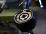
i've finished one side and its much better now... very tight:
blog post detail
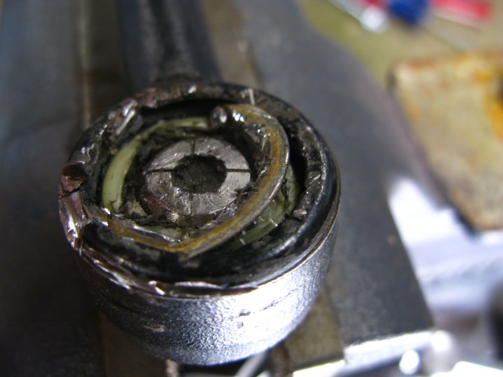
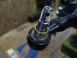
something odd i noticed: there are four "lumps" in the pin arranged at 12, 3, 6, & 9 o'clock on two different surfaces: the "nose" where the flanged bearing surrounds:

*
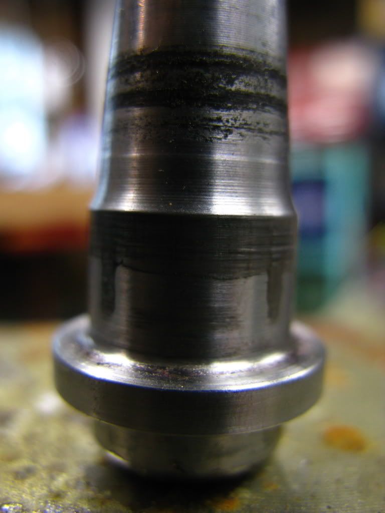
and the "butt" that faces the cap:

see them? how would these have been formed? surely after machining...right? why? what are they for? they seem to be preventing a perfectly smooth rotation, but as the pin only moves through...25º?...probably doesnt matter. still curious, though.
a couple impressions for anyone else about to take this on:
1. measure the gap between the arms first, before you cut anything!
2. the cap is crazy thick for what it is and really on there...if your nylon is still in good shape like mine was, you wont have any "wiggle room" and it will take considerable Dremel action to get even a sliver out.
3. shop around...some hardware stores have crazy high prices.
i found a store with prices roughly 50% of where i was shopping, and picked up a pair of the flanged bearings for just over a dollar each...i had actually bought one already a few days ago but wrecked it by tapping it onto the pin before i was done sanding; it cracked.
i've finished one side and its much better now... very tight:

blog post detail
something odd i noticed: there are four "lumps" in the pin arranged at 12, 3, 6, & 9 o'clock on two different surfaces: the "nose" where the flanged bearing surrounds:
*
and the "butt" that faces the cap:
see them? how would these have been formed? surely after machining...right? why? what are they for? they seem to be preventing a perfectly smooth rotation, but as the pin only moves through...25º?...probably doesnt matter. still curious, though.
a couple impressions for anyone else about to take this on:
1. measure the gap between the arms first, before you cut anything!
2. the cap is crazy thick for what it is and really on there...if your nylon is still in good shape like mine was, you wont have any "wiggle room" and it will take considerable Dremel action to get even a sliver out.
3. shop around...some hardware stores have crazy high prices.
-
raygreenwood
- Posts: 11914
- Joined: Wed Jan 22, 2003 12:01 am
Did I send you the pictures of my centerlink parts? they are worth inspecting to get an idea of some subtle things I did.
(1) inside of the bore in the joint the bottom area where teh hole for the pin is....has rounded edges. The original plastic was rounded on teh nose to pack that space exactly.
(2) the flanged bearing I put in there...also had rounded edges to fit that space and "pack it".
I round bearings and sanded washers...by installing them in a threaded shaft with lock nuts and installing them in a drill held in a vice. Then while they were turning..I used sanding drums on my dremel against the edges. In this way I was very quickly able to reduce diameter sises. ID's...were harder I used smaller (7mm?) sanding drums and 13mm sanding drums on the dremel and oocasionally emory stone bits. Heavy removal of ID was done with a carbide cutter. Very fast...but for Gods sake wear glasses and long sleeves and run a vacuum. the shards are murder.
(3) In the pictures of my parts you can see that the top most bronze washer on the pin inside of the joint...is a flanged bearing with a very short cuff. the cuff extends only flush with the outside deck....where another flanged bearing and a single bronze washer sits on the outside to take up the space between the joint and the pitman arm.
Both the inner and outer flanged bearings strted with ID too small for the pin...and I tapered them with the dremel tools and saning drums. Tedious...but a dead fit. Ray
-
Lahti411
- Posts: 128
- Joined: Sat Jan 29, 2005 2:23 pm
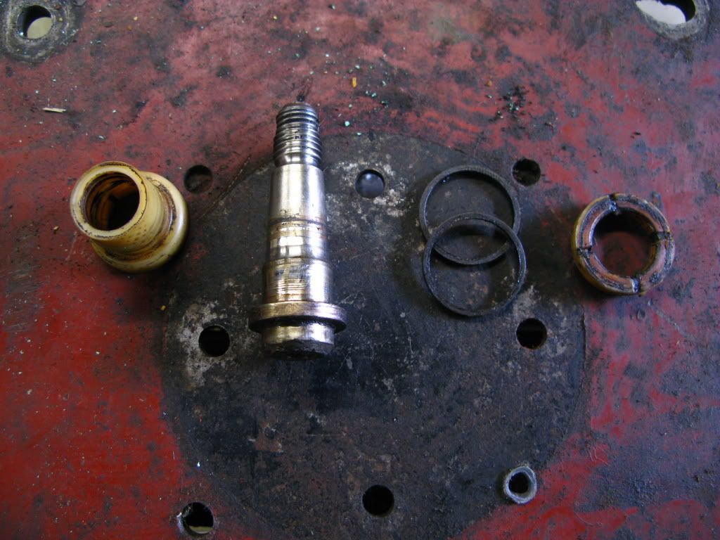
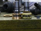
I'm rebuilding another centerlink so i took some pics of the parts i made for it.
Bronze bushings

Rounded edge on the lower bushing that fits against the centerlink

Upper bushing 5mm thick

Lower bushing 6mm thick

Assembled

Fitted inside the centerlink

Cap and snap ring

I haven't yet made the collar-bushing for the pin and its next on the list.
Bronze bushings
Rounded edge on the lower bushing that fits against the centerlink
Upper bushing 5mm thick
Lower bushing 6mm thick
Assembled
Fitted inside the centerlink
Cap and snap ring
I haven't yet made the collar-bushing for the pin and its next on the list.
-
raygreenwood
- Posts: 11914
- Joined: Wed Jan 22, 2003 12:01 am
Nice! All of you guys got it. Once you get things packed in....and packings are a very good term for what these parts are...just like a valve packing,....we can rebuild these joints and have excellent parts.
What did you use for the black band around the middle? I used a strip of teflon I had laying around. The only real reason for having anythingg there...is simply to spread out load. Ray
What did you use for the black band around the middle? I used a strip of teflon I had laying around. The only real reason for having anythingg there...is simply to spread out load. Ray
-
wshawn

- Posts: 209
- Joined: Thu Dec 27, 2007 6:36 am
I keep on looking at this thread now I have my spare centrelink at home and hopefully I should be able to make a start on it just as soon as my kids return to school after the Easter break.
First I need to seperate it from the other steering linkages it came with. Would taking the measurements on the gaps between the centrelink and the pitman/idler arms it is currently attached too be suffecient to make the bushes to transfer it to the steering parts on my car, or are they likely to be radically different?
I can then cut the thing apart to measure up the bits to source the bronze bushes/washers needed to replace the old bushes, I think I have found somewhere local for these parts now.
Although I hope I haven't left replacing it to long as my 412 has developed the wheel wobble again despite the parts changed last year. Strangely it seems to have got noticably worse after the MoT (Ministry of Transport roadworthiness test) which involved some rather violent shaking on the front end by the testers new testing machine. This machine placed plates under the front wheels and shook/bounced the front end whilst progressivly turning the steering towards each lock. It's the first time I've seen them use this and it was a tad nerve-racking. Thankfully he didn't find anyhting to fail the car on though, so another years ticket was obtained.
However, back to the wheel wobble/steering vibration, I'm hoping the shaking was just hastening the end of the bushes in the centrelink and it hasn't damaged anything else.
I know I should have changed this last year but, due to one thing or another, never quite got around to it.......
Mustn't forget to say I'm impressed by the work you lot have done, just hope I can do it some justice too once I get started.
-
Lahti411
- Posts: 128
- Joined: Sat Jan 29, 2005 2:23 pm
I used the original plastic centering rings as they were in great shape and were obviously perfect fit.What did you use for the black band around the middle? I used a strip of teflon I had laying around. The only real reason for having anythingg there...is simply to spread out load. Ray
When i opened the first centerlink i didn't have any pics of how to do it as STF had just crashed and the great photos on the original centerlink rebuild thread were vanished. I didn't remember that the pictures Ray had taken showed that you can cut the grease cap by making slits that reach over the cavity wall (hope you'll understan what i mean). This way the cap would have already been in four pieces so it would have been easier to pul those last bits of the butchered grease cap out. So i just cut the grease cap as much as i could, with just about every Dremel tool i could find, until there was only a thin ring left. Then i strated to twist, push, pul and wiggle the ring out of its groove until it finally gave up and came out. I think it took something like two evening just to get both grease caps out...
And now whe i opened the second centerlink i did just the same as described above... I just thought that the centerlink looked better this way... Like somebody was going to see it...
But anyway it's surprisingly tedious job to get the grease cups out but after that it's all simple and you'll see instantly what needs to be done and why.