Parallel front King Pin Suspension
-
CentralWAbaja

- Posts: 4291
- Joined: Fri Feb 05, 2010 9:05 pm
Re: Parallel front King Pin Suspension
My car runs a parallel beam. But I'm not sure what I can give you in pros and cons department. There is just so much more going on with mine, and I changed so many things when I went to this beam that it was just 1 part
It is not Mickey Moused.....It's Desert Engineered!
-
woodsbuggy1
- Posts: 826
- Joined: Sun Feb 20, 2011 5:15 pm
Re: Parallel front King Pin Suspension
Thanks for the input, I will stop thinking about it and order tubing so I can build a parallel beam.
Kenric
Kenric
Good quality is getting harder and harder to find.
-
Ol'fogasaurus
- Posts: 17881
- Joined: Mon Nov 13, 2006 10:17 pm
Re: Parallel front King Pin Suspension
Silly, but don't get seamed tubing as it has weaknesses plus the forming is different as I remember.
https://www.bing.com/search?q=formed+tu ... 36&pc=LCTS
I have seen welded tubing done in a lot of things that required the strength of formed tubing. Price differences and availability between the two is another factor.
Lee
https://www.bing.com/search?q=formed+tu ... 36&pc=LCTS
I have seen welded tubing done in a lot of things that required the strength of formed tubing. Price differences and availability between the two is another factor.
Lee
-
Ol'fogasaurus
- Posts: 17881
- Joined: Mon Nov 13, 2006 10:17 pm
Re: Parallel front King Pin Suspension
The term "buggy" covers a lot of different things mostly a VW pan (shortened or stock length) or a tube rail, both can have bodies.
I did some more looking around, this time at the "combo spindles" and re-read the original post, what you are planning sounds good.
The taper in you asked about is basically from the "fire wall" to the beam's connections which can be many distances due to wheel base options. I posted the stock buggy pan for reference: the rear area is the passenger and the start of the front seat area. The first taper in is the doorway which is roughly from the front seat to the dash then the last is the taper from the firewall to the beam. If you are building a "tube rail" a lot of this applies but a bit differently.
"Cause and effect":
If you have the seats already and a cement floor that is open then put the seats down with the planned spacing between them. This would be for the shifter and shift rod (access), turning brakes if you are using them and seat to seat spacing covering arm movement of the driver and a rider if there is one and seat belt access as when you get out the belts usually drop in-between the seats
 .
.
Using chalk mark the seats located then mark where your feet are when pushing the clutch pedal (on the floor or hanging) and pressing the "loud pedal". This will give you a start at locating the beam, the cage and where the trans and rear suspension and other components would/could be located. I would then draw things on a piece of paper with dimensions (so you don't lose info and chalk can disappear). What you want to do is probably going to change over time and before you start doing the "expensive" stuff so each change, do a paper but keep the old ones also incase things change in another direction or back again. Also, depending on what your state's laws are you might be required to have parking brakes so the handle there is also a determining factor (I would not use the rear wheel hydraulics for the parking brakes. My blue Manx style of dune buggy had them when I bought it and the unit did lose the lock and the buggy rolled down a driveway backwards and did damage to the body. Many states do not allow this type of unit).
The metal firewall in a tube buggy (with the engine, trans and probably the fuel tank is in the rear) usually doesn't exist but the access to the location of the pedals (on the floor or hanging) is the determining factor. This is all basic stuff, but it is what needs to be covered when planning a new toy.
I don't have a rail but there has been a couple in our group, and I have seen new designs in some of the groups that we know. What they come up with is pretty interesting most of the time, but I have seen a couple "toys" that keep being changed all the time due to either updates or fixing things they thought didn't matter.
Your idea of planning so far ahead is a good thing to do but... "get er done"!
Lee
I did some more looking around, this time at the "combo spindles" and re-read the original post, what you are planning sounds good.
The taper in you asked about is basically from the "fire wall" to the beam's connections which can be many distances due to wheel base options. I posted the stock buggy pan for reference: the rear area is the passenger and the start of the front seat area. The first taper in is the doorway which is roughly from the front seat to the dash then the last is the taper from the firewall to the beam. If you are building a "tube rail" a lot of this applies but a bit differently.
"Cause and effect":
If you have the seats already and a cement floor that is open then put the seats down with the planned spacing between them. This would be for the shifter and shift rod (access), turning brakes if you are using them and seat to seat spacing covering arm movement of the driver and a rider if there is one and seat belt access as when you get out the belts usually drop in-between the seats
Using chalk mark the seats located then mark where your feet are when pushing the clutch pedal (on the floor or hanging) and pressing the "loud pedal". This will give you a start at locating the beam, the cage and where the trans and rear suspension and other components would/could be located. I would then draw things on a piece of paper with dimensions (so you don't lose info and chalk can disappear). What you want to do is probably going to change over time and before you start doing the "expensive" stuff so each change, do a paper but keep the old ones also incase things change in another direction or back again. Also, depending on what your state's laws are you might be required to have parking brakes so the handle there is also a determining factor (I would not use the rear wheel hydraulics for the parking brakes. My blue Manx style of dune buggy had them when I bought it and the unit did lose the lock and the buggy rolled down a driveway backwards and did damage to the body. Many states do not allow this type of unit).
The metal firewall in a tube buggy (with the engine, trans and probably the fuel tank is in the rear) usually doesn't exist but the access to the location of the pedals (on the floor or hanging) is the determining factor. This is all basic stuff, but it is what needs to be covered when planning a new toy.
I don't have a rail but there has been a couple in our group, and I have seen new designs in some of the groups that we know. What they come up with is pretty interesting most of the time, but I have seen a couple "toys" that keep being changed all the time due to either updates or fixing things they thought didn't matter.
Your idea of planning so far ahead is a good thing to do but... "get er done"!
Lee
-
BAJA-IT
- Posts: 2046
- Joined: Tue Oct 07, 2008 5:02 pm
Re: Parallel front King Pin Suspension
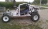
I am in the process of building a parallel beam for my baja.
Stock width with 2.5 longer arms & combo spindles.
I will be pushing the beam forward 4.5 inches.
It's still winter here in Utah , so it will be a few months before I can get it installed.
Car is outside.
Stock width with 2.5 longer arms & combo spindles.
I will be pushing the beam forward 4.5 inches.
It's still winter here in Utah , so it will be a few months before I can get it installed.
Car is outside.
BRAT Motorsports #936
Bolt Center: Salt Lake City, Ut
ACE: Air Cooled Engineering, now Black Line Racing
Bolt Center: Salt Lake City, Ut
ACE: Air Cooled Engineering, now Black Line Racing
-
woodsbuggy1
- Posts: 826
- Joined: Sun Feb 20, 2011 5:15 pm
Re: Parallel front King Pin Suspension
Baja-IT, please share your conversion with us, hopefully you post a thread.
Lee, I just ordered 1020 DOM .250 wall tubing for my beam, hopefully that will suffice.
Kenric
Lee, I just ordered 1020 DOM .250 wall tubing for my beam, hopefully that will suffice.
Kenric
Good quality is getting harder and harder to find.
-
CentralWAbaja
- Posts: 4291
- Joined: Fri Feb 05, 2010 9:05 pm
Re: Parallel front King Pin Suspension
In my opinion the bottom tube should be .250 but the top tube can be .120 wall. Pretty common setup for the race car beams.woodsbuggy1 wrote: ↑Tue Jan 23, 2024 12:33 pm Baja-IT, please share your conversion with us, hopefully you post a thread.
Lee, I just ordered 1020 DOM .250 wall tubing for my beam, hopefully that will suffice.
Kenric
It is not Mickey Moused.....It's Desert Engineered!
-
Ol'fogasaurus
- Posts: 17881
- Joined: Mon Nov 13, 2006 10:17 pm
Re: Parallel front King Pin Suspension
Don't forget to put a perpendicular "bridge plate" on the shock tower (if used) to support any torquing of the shock load on the beam if still connected to the beam. It might be a good idea to double up on the hole for the shock's bolt as a "just-in-case thing" especially if you are using a combo shock and spring setup. Some of those "bangs and bumps" can get pretty rough out there.
Lee
Lee
-
Ol'fogasaurus
- Posts: 17881
- Joined: Mon Nov 13, 2006 10:17 pm
Re: Parallel front King Pin Suspension
I'm kind of having fun with this (not meant to be negative).
Thinking back at things I have seen over the years on the sand (et al) especially those that have failed, or I see things that potentially could help.
On the floors, people sometimes put something like a wire mesh that allows the sand and/or dirt to drop back out but the problem I see it that other than that it doesn't do much else strength wise.
I think I would recommend that if you put a sheet of metal down that you see if you can have it "bead rolled" and flanged in places for additional strength and for mounting to the tubing. I also have seen the flooring only go to the areas where help getting in or some mounting of things. An example would be the floors only go past the seat front, maybe back to the seat's front mount which would allow the sand and stuff to be easily removed.
A couple of times (in the past) I have seen bent up pieces of flat stock (flooring probably) that looked like they just dropped off the toy not to be seen by the driver/passenger again.
Cutting holes in flat stock and not flanging the (for example the holes for fasteners usually doesn't count here) can cause the weakening of the metal to bend or tear. Also, for what it is worth: if you are going to put a string of holes in, in rows, offset the holes in the rows.
For example, you have planned on 4 rows of holes: the first row is OK, but the next row should be off set, say between the gap between the first row of holes. The third row of holes can be the same as the first row, then the fourth row would be located like the second row. This sounds complicated but the strength it gives and the potential damage it protects is worth it. It is the straight line between the lines of holes you are eliminating that can cause bending problems.
Also, since this is a floor then the flanging of the holes should be facing down.
Even with only two rows the offset is a good idea.
The beading also strengthens the flat stock but facing up otherwise it holds the dirt inside setting things up for rust.
https://www.bing.com/search?q=flanging+ ... ba&pc=LCTS
Simple things but worth thinking about ("stuff" I had to deal with when I was working).
Lee
Add'll info.
I used the word flanging which is usually 90 degrees. "Dimpling" is in the 30 to 45 degree angle. "Dimpling can fail and you would/could see creases on one side of the dimple or on 2 sides of the flange. There are (usually) different reason's for each, the dimpling or flanges and it is based on different amounts "loading" or material for example.
Looking it up is going to give you a lot of different information some of it better than others depending....
Lee
Last edited by Ol'fogasaurus on Wed Jan 24, 2024 9:29 pm, edited 1 time in total.
-
Ol'fogasaurus
- Posts: 17881
- Joined: Mon Nov 13, 2006 10:17 pm
Re: Parallel front King Pin Suspension
Be careful in your rebuild as things can be missed.
Lee
Lee
You do not have the required permissions to view the files attached to this post.