Reds are battery in (30)
Blacks are Ignition out (15) (on in position 2 & 3 only)
Yellow is Starter(relay)(50) (on in positions 3 only)
Black/Yellows are Accessories(X) (on in positions 1 & 2 only)
Red/Black(thick) is Radio Supply (on in Positions 1,2,3)
Red/Black(thin) is power in (30) to key-in switch
Grey is Off (on in Position 0 - key in or out)
Black/Red is key-in switch output(*) (on when key is in)
Switch Position
* Key Out
0 Inserted only
1 Accessory Only
2 Ignition
3 Starter
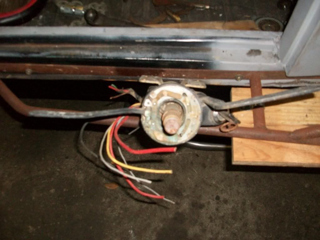
My wire colors aren't quite matching up on the Porsche Ignition switch.
http://www.356-911.com/912restogallery/ ... big912.gif
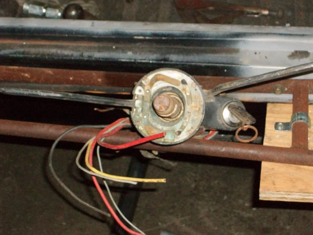
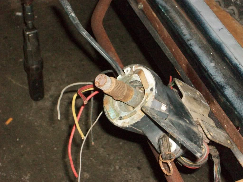
My Ignition Switch has 7 wires.
I tested the switch with an OHM Meter and these are the results I got. I am not understanding why I have no continuity in any position on the gray wire with red stripe, see the Bold Red High Lighted text below.
Large Red wire = Power in to switch
Large Yellow wire = Input to Starter
Medium Red wire = Power with Key On Only (I am thinking I can use this to turn on lighting)
Large Black wire = Power with Key On and Start (I am thinking I can use this to power up the fuse panel)
Small Gray wire = Power with Key Off Only (most likely for dome light, when door is open)
Small Gray wire with Red Stripe No Continuity to power in any position (most likely ground for key buzzer)
Small Black wire = Power Key On and Start ( I am thinking of using this for the Parking Lights)
Porsche Turn Signal Wiring
Gray 57A goes to Ignition Switch from Turn Signal
Black/Green/White 49A goes to Turn Signal Flasher
Red 30 goes to Ignition Switch and Head Lamp Switch
Gray/Black 57L goes to Fuse #8 (Left Parking Light)
Gray Red 57R goes to fuse # 7 (Right Parking Light)
Black/White 49L goes to LR and LF Turn signals
Black/Green 49R goes to RR and RF Turn Signals
Brown/White 82 goes to Horn Relay
Brown goes to Ground
Hot, humid air is less dense than cooler, drier air. This can allow a golf ball to fly through the air with greater ease, as there won't be as much resistance on the ball.
