
Whats Wrong With This Picture
-
mountainkowboy
- Posts: 341
- Joined: Fri Aug 30, 2013 12:57 pm
Whats Wrong With This Picture
Started stripping the verts pan..........some people shouldn't own a VW.
71 Ghia Coupe........For Sale
71 Super-Beetle Convertible.....returning to DD status
63 IH Scout 80 (beater)

71 Super-Beetle Convertible.....returning to DD status
63 IH Scout 80 (beater)
-
Marc

- Moderator
- Posts: 23741
- Joined: Thu May 23, 2002 12:01 am
Re: Whats Wrong With This Picture
Are you referring to the placement of the washers? That is correct, both go on the outside. Don't ask me why.
http://www.1800vw.bizhosting.com/0.susp ... ar.irs.htm
http://www.1800vw.bizhosting.com/0.susp ... ar.irs.htm
-
mountainkowboy
- Posts: 341
- Joined: Fri Aug 30, 2013 12:57 pm
Re: Whats Wrong With This Picture
Really...................than the other ones that I've taken apart were wrong......lol
71 Ghia Coupe........For Sale
71 Super-Beetle Convertible.....returning to DD status
63 IH Scout 80 (beater)
71 Super-Beetle Convertible.....returning to DD status
63 IH Scout 80 (beater)
-
Marc
- Moderator
- Posts: 23741
- Joined: Thu May 23, 2002 12:01 am
Re: Whats Wrong With This Picture
It's baffling, the early Bentley manuals showed one washer on each side and the later ones show both outside - and the text is no help, it only says to put them back where they came from.
Ironically, the 1969 "Without Guesswork" workshop manual published for VW states that the rear wheel toe-in should be 10' ± 10', while the 1972 booklet calls for 0° ± 15'. The camber spec remained at -1°20' but the tolerance was opened up from ± 30' to ± 40'; the side-to-side maximum deviation was loosened up too, from 30' to 45'. One might infer that, unless there was a change made to the pivot points or control arm dimensions, it was found that there was insufficient toe-in with one washer on each side so they took the easiest possible route to "fix" it and put them both outboard...then, when that was still not quite enough, changed the published specs to match the reality...but I asked you not to ask me that
I just put them both on the outside and check that the toe can be set to 0°. If I ever encountered a car that had too much toe-in that way I'd have no qualms about moving a washer inboard on one side or both, but it hasn't happened yet.
-
Ol'fogasaurus
- Posts: 17881
- Joined: Mon Nov 13, 2006 10:17 pm
Re: Whats Wrong With This Picture
Reverse engineering can be kind of hard to do sometimes especially after all the years since VW (et al) started to play with 4-joint IRS.
Washers can be used for a number of reasons such as: a spacer(s) (3 max before going to a single thicker spacer. The reason for this is that the washers can get out of line during installation which can reduce the amount of load the fastener head is applying to the surface), for load bearing/distributing or protection of other contacting surfaces just to name a few.
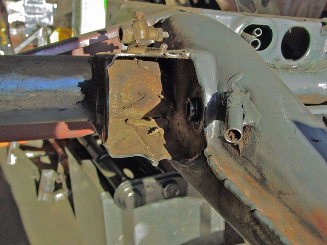
On the inside of the pivot mount there is a smooth face for the rubber part of the busing to ride against. The bushing rides on the tang so the inside surface is taken care of for load an protection. If you look closely you can see the surface that the rubber mount rides against and the "tang".
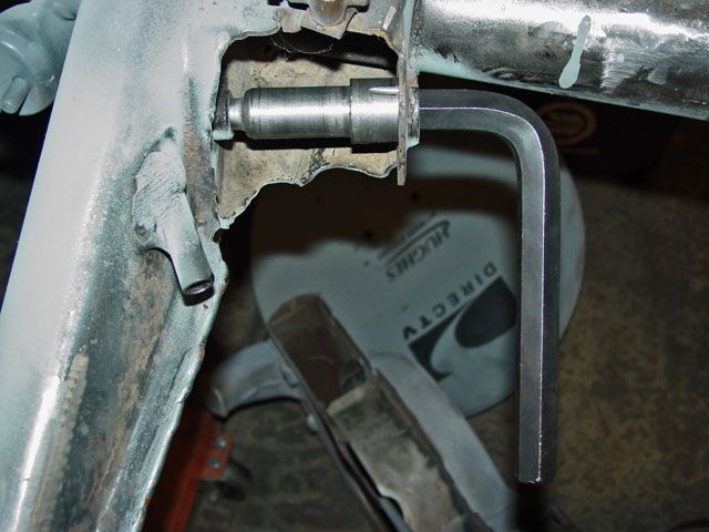
The bolt slides through the outside of the bracket through a flanged hole, through the two washer and through the trailing arm and threaded into the tang on the inside of the mount and torqued in place then "staked". Notice that the threaded part of the shoulder bolt stops short of the full length of the non-shoulder part of the bolt.
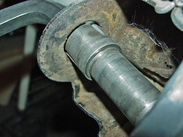
This shows the bolt in place w/o the trailing arm or washers installed. Notice in this case that the shoulder bolt's head is almost even with the outer flange of the mounting bracket. The bolt does not totally "bottom out": use up all of the threads during installation
Of the two outside washers: the inner washer rides against the rubber bushing mount (probably) to protect it from the head of the bolt and I suspect that the outer washer has a two fold job as a spacer and protection for the inner washer from the bolt head especially if the pivot bolt loosens up (you never know what happened during testing during the design process or during the design review meetings). The question I still have is that when removing the trailing arm I haven't seen any signs of the two washers moving against each other.
Am I correct... probably not but it does make some kind of sense (in my opinion of course ). My VW manual does say both washers to the outside but my first VW came with a washer on each side of the pivot plus three other thinner spacer washers. The two washers to the outside does make more sense to me. The washer to the inside just means that there is going to be less of the "tang" for the bushing in the trailing arm to ride on.
My opinion is worth slightly less than you paid for it.
Lee
Washers can be used for a number of reasons such as: a spacer(s) (3 max before going to a single thicker spacer. The reason for this is that the washers can get out of line during installation which can reduce the amount of load the fastener head is applying to the surface), for load bearing/distributing or protection of other contacting surfaces just to name a few.

On the inside of the pivot mount there is a smooth face for the rubber part of the busing to ride against. The bushing rides on the tang so the inside surface is taken care of for load an protection. If you look closely you can see the surface that the rubber mount rides against and the "tang".

The bolt slides through the outside of the bracket through a flanged hole, through the two washer and through the trailing arm and threaded into the tang on the inside of the mount and torqued in place then "staked". Notice that the threaded part of the shoulder bolt stops short of the full length of the non-shoulder part of the bolt.

This shows the bolt in place w/o the trailing arm or washers installed. Notice in this case that the shoulder bolt's head is almost even with the outer flange of the mounting bracket. The bolt does not totally "bottom out": use up all of the threads during installation
Of the two outside washers: the inner washer rides against the rubber bushing mount (probably) to protect it from the head of the bolt and I suspect that the outer washer has a two fold job as a spacer and protection for the inner washer from the bolt head especially if the pivot bolt loosens up (you never know what happened during testing during the design process or during the design review meetings). The question I still have is that when removing the trailing arm I haven't seen any signs of the two washers moving against each other.
Am I correct... probably not but it does make some kind of sense (in my opinion of course
My opinion is worth slightly less than you paid for it.
Lee
-
helowrench
- Posts: 1925
- Joined: Wed Aug 11, 2004 6:20 am
Re: Whats Wrong With This Picture
When I had the ghia apart for bushings, i put it back together the way it came apart. Since I had no funky tire wear from the rear after 100k miles.
-
Ol'fogasaurus
- Posts: 17881
- Joined: Mon Nov 13, 2006 10:17 pm
Re: Whats Wrong With This Picture

This is the stack that came off of the one side. The two big washers seem to be the same thickness (I didn't mike them) but the diameter if the inside holes were different; the other trailing arm was a normal stack of parts. The pan is still apart (my black buggy) but so much of the car was hashed up I am sure this was just another of the cobble jobs by one of the previous POs.
The three extra washers are so thin they didn't seem to do much. When I put things back together for a check fit after rebuilding the trailing arms both of the sides bolted together, w/o the three shims, and the bolt head were about the same distance down the flanged hole.
If the bushing assembly on the pivot end of the trailing arm is OK and the right thickness plus the torsion bushings are fitting properly I don't see why moving the washers around is going to be necessary... but then what do I know
The outside flanged hole is not that tight of a fit so there is/can be some (agreed probably minor) deflection of the bolt which translates to the trailing arm.
Lee
-
helowrench
- Posts: 1925
- Joined: Wed Aug 11, 2004 6:20 am
Re: Whats Wrong With This Picture
Foggy, the spring plate will be carrying most or all of the vehicle weight loading, this diagonal arm carries a load similar to your tie rods (just keeping the wheel pointed in the desired direction. Tie rod ends are pretty much same dia as the diag arm bolt.
-
Ol'fogasaurus
- Posts: 17881
- Joined: Mon Nov 13, 2006 10:17 pm
Re: Whats Wrong With This Picture
... except for side loads which is what damages the trailing arms most of the time. Anytime you don't land flat or bounce off or against something you are putting loads sideways into the trailing arms and the pivots or that is what I have been told and seen. Reading some of the write-ups on the installations of the pivots also makes me think there is more to what is going on there than a casual thought might give. Anyway, it is my opinion and I already have made a disclaimer on what my opinion is worth.
Lee
Lee
-
helowrench
- Posts: 1925
- Joined: Wed Aug 11, 2004 6:20 am
Re: Whats Wrong With This Picture
True, I would rather have a nice Heim joint in a double sided cage. I will have to see what the 924/944 hardcore racers are doing.
-
mountainkowboy
- Posts: 341
- Joined: Fri Aug 30, 2013 12:57 pm
Re: Whats Wrong With This Picture
WOW.........that's a lot of information! I will be taking it apart (again), it seems like it 1 step forward and 2 steps back lately. I have decided to use the trailing arm assemblies from the verts pan, close inspection yesterday reviled that everything is new and nice and tight, bearings, brakes, and drums. It just seems easier to change the whole arm rather than parts.
I also have to remove the tie rod arm from the front since I cant get the jam nuts loose to adjust them...I knew I should have taken everything apart and cleaned it up.
I also have to remove the tie rod arm from the front since I cant get the jam nuts loose to adjust them...I knew I should have taken everything apart and cleaned it up.
71 Ghia Coupe........For Sale
71 Super-Beetle Convertible.....returning to DD status
63 IH Scout 80 (beater)
71 Super-Beetle Convertible.....returning to DD status
63 IH Scout 80 (beater)
-
Ol'fogasaurus
- Posts: 17881
- Joined: Mon Nov 13, 2006 10:17 pm
Re: Whats Wrong With This Picture
If you think about it, the combination of the trailing arm, the spring plate and the torsion tube you have a soft sided triangle with the spring plate being the soft part of the one side.
Several years ago one of our STF guys sent me three single arm spring plates (I had double arm but the trailing arms I had were for a single arm spring plate)... thank you, thank you, thank you! As I remember, at least two of them were bent (he didn't know how as he had lent them to someone else) so, assuming that the bends were not out of orneriness, there can be some brutal deflections than can be applied to this triangle. A couple of measured whacks with a 3#er laying on a section of RR track, in the proper location and each spring plate was straightened out. As I remember, one of them actually had two bends in it. You don't want to beat on them any more than the couple of fairly light whacks as they are spring steel. Do not compact the metal beating the crap out of it nor do you want to apply heat as 400° can turn the spring steel into mild steel.
As far as Heim-joints/spherical rod ends are concerned there are (should be) limits to their use. They are easily miss-used which can make them suspect for certain uses. Tie-rods are designed especially for miss-alignment like this... up to a point that is. I have seen some very unique applications/uses using spherical rod ends that were super strong (over 16Gs and that was carrying a lot of weight to start with).
Lee
Several years ago one of our STF guys sent me three single arm spring plates (I had double arm but the trailing arms I had were for a single arm spring plate)... thank you, thank you, thank you! As I remember, at least two of them were bent (he didn't know how as he had lent them to someone else) so, assuming that the bends were not out of orneriness, there can be some brutal deflections than can be applied to this triangle. A couple of measured whacks with a 3#er laying on a section of RR track, in the proper location and each spring plate was straightened out. As I remember, one of them actually had two bends in it. You don't want to beat on them any more than the couple of fairly light whacks as they are spring steel. Do not compact the metal beating the crap out of it nor do you want to apply heat as 400° can turn the spring steel into mild steel.
As far as Heim-joints/spherical rod ends are concerned there are (should be) limits to their use. They are easily miss-used which can make them suspect for certain uses. Tie-rods are designed especially for miss-alignment like this... up to a point that is.
Lee