Mid engine 66 bug subaru powered
-
Ol'fogasaurus
- Posts: 17881
- Joined: Mon Nov 13, 2006 10:17 pm
Re: Mid engine 66 bug subaru powered
How do you plan on supporting the trans mount? The stock trans mount you are connected to by some tubes already has a rep for doing the "dance of death" which is why Kaffer/Truss/Traction Bars are added.
Lee
Lee
You do not have the required permissions to view the files attached to this post.
-
maurice
- Posts: 105
- Joined: Sun Apr 03, 2016 10:49 am
Re: Mid engine 66 bug subaru powered
Good observation. There is actually very little weight supported by the frame horns. The majority of it is under the rear of the engine. That part is supported by a large and well supported 1/4” plate. The engine essentially leverages the tranny up, so there’s maybe 70lbs of weight supported between the two frame horns (more with the sti tranny). I plan to mount a wing off of the tube near the tranny, so the horns will get stressed more, but still far less than the weight of an engine hanging off the end of them like in the stock setup.
The structure is also now a rectangle since it’s bolted all together with the round structure on top of it. So twisting the two frame horns would also require the round tubing to also twist.
They’re mostly there for stability, but also provide a solid support should I happen to stress the mount
The structure is also now a rectangle since it’s bolted all together with the round structure on top of it. So twisting the two frame horns would also require the round tubing to also twist.
They’re mostly there for stability, but also provide a solid support should I happen to stress the mount
-
Ol'fogasaurus
- Posts: 17881
- Joined: Mon Nov 13, 2006 10:17 pm
Re: Mid engine 66 bug subaru powered
Since my rig is set up to do different things I look at things differently too. I'm fighting the same area on the rear of the car myself.
Lee
Lee
-
maurice
- Posts: 105
- Joined: Sun Apr 03, 2016 10:49 am
Re: Mid engine 66 bug subaru powered
I definitely had to stabilize that part of the car with the turbo engine and vw tranny. It’s an issue, but can also be solved with a hydraulic clutch
-
maurice
- Posts: 105
- Joined: Sun Apr 03, 2016 10:49 am
Re: Mid engine 66 bug subaru powered
Not the prettiest job, but everything is removable now! Should be easy to get the engine in and out now
You do not have the required permissions to view the files attached to this post.
-
maurice
- Posts: 105
- Joined: Sun Apr 03, 2016 10:49 am
Re: Mid engine 66 bug subaru powered
Rolled it around the neighborhood a bit yesterday. Only did low speed stuff, but no understeer when I put my foot in it around a corner. Tranny doesn’t like to shift well, might need to modify my shifter linkage a tiny bit. Suspension might be on the stuff side, I’ll have to start playing with the adjustments and maybe lose the sway bar
Then I can start working on under car aero stuff, and sealing off the engine from the occupants.
Then I can start working on under car aero stuff, and sealing off the engine from the occupants.
You do not have the required permissions to view the files attached to this post.
-
kdf
- Posts: 110
- Joined: Fri Jun 03, 2005 5:37 am
Re: Mid engine 66 bug subaru powered
I think you should do a basic calculation to verify suspension loads. The inner and outer joint rod end in bending look off.
I have used 10 % load for spherical bearing axial load, but only used quality spherical bearings. In rod end calculation you should also take into consideration how much the rod end can take bending. The strength of the rod end depends on how much rod end is sticking out.
In production cars calculated loads are in the ballpark of 5g bump, 4g longitudinal and 3g lateral. In prototype cars it is less.
You do not have the required permissions to view the files attached to this post.
-
maurice
- Posts: 105
- Joined: Sun Apr 03, 2016 10:49 am
Re: Mid engine 66 bug subaru powered
I couldn’t really find stickout numbers for the threaded part, but the heim joints are rated to 28,090lbs static load each, which at 10% for all 4 translates to 11,236lbs for axial load.
The entire car weighs 2000lbs, so even if the rear had 75% of the weight on it, the working static limit would be 7.5g’s. I know that that static load and a load I experience while driving wouldn’t be the same, but I don’t think my tires could handle that kinda load and grip.
The entire car weighs 2000lbs, so even if the rear had 75% of the weight on it, the working static limit would be 7.5g’s. I know that that static load and a load I experience while driving wouldn’t be the same, but I don’t think my tires could handle that kinda load and grip.
Last edited by maurice on Sun May 03, 2020 1:18 pm, edited 1 time in total.
-
maurice
- Posts: 105
- Joined: Sun Apr 03, 2016 10:49 am
Re: Mid engine 66 bug subaru powered
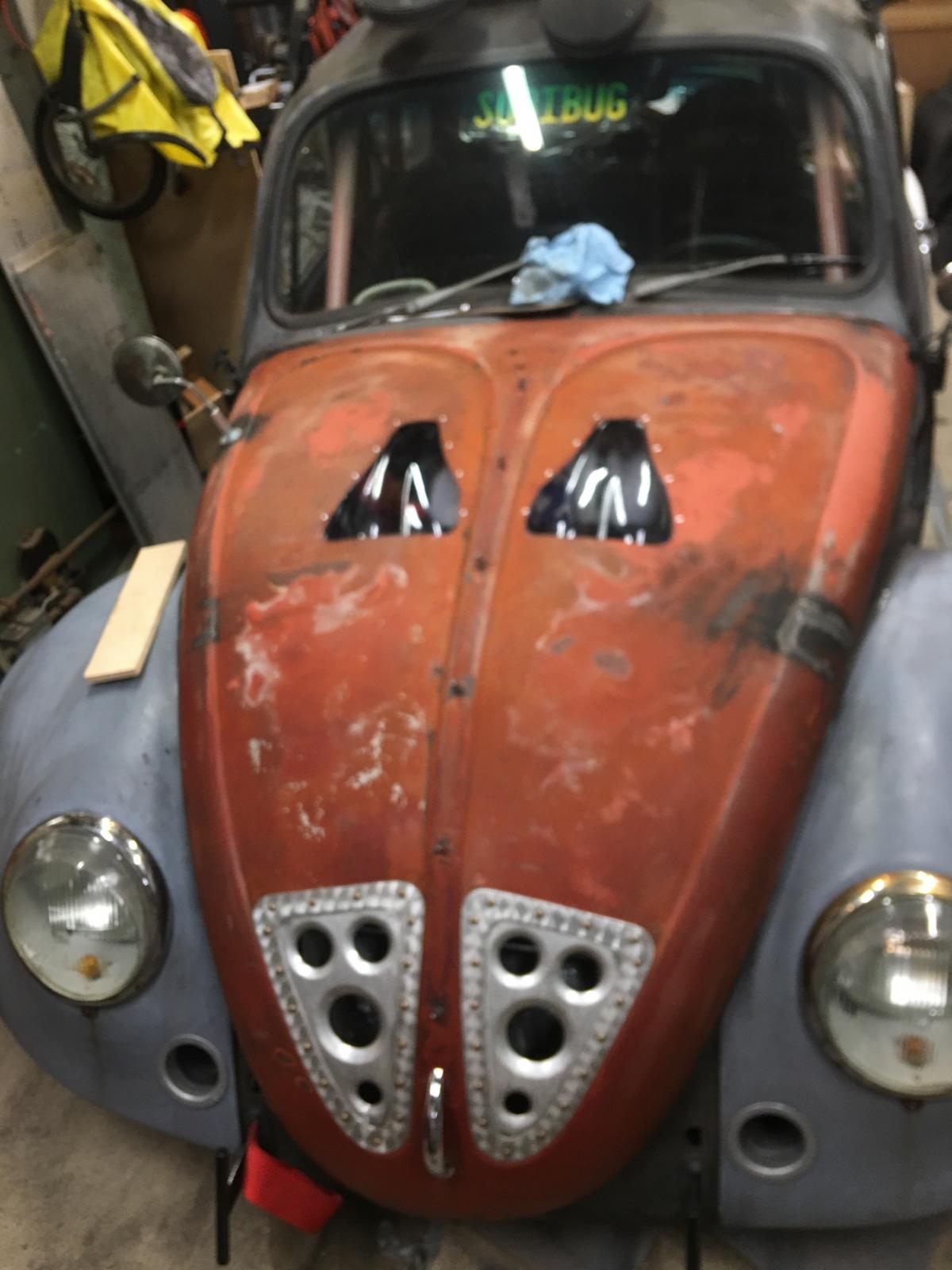
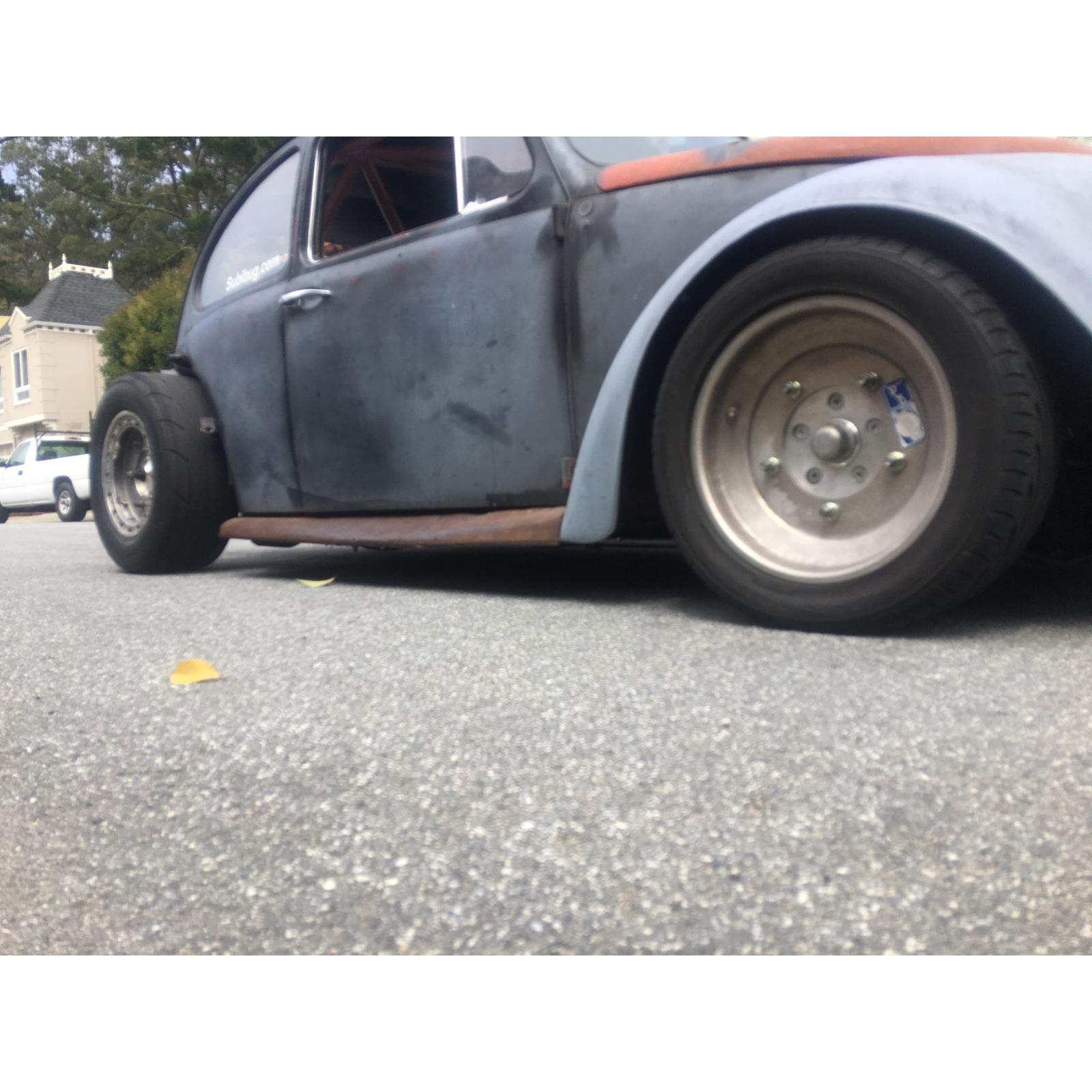
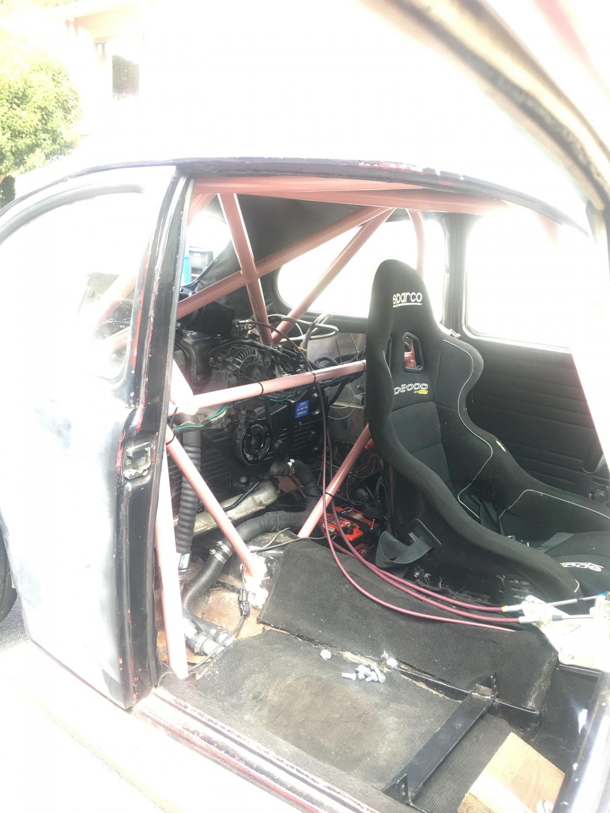
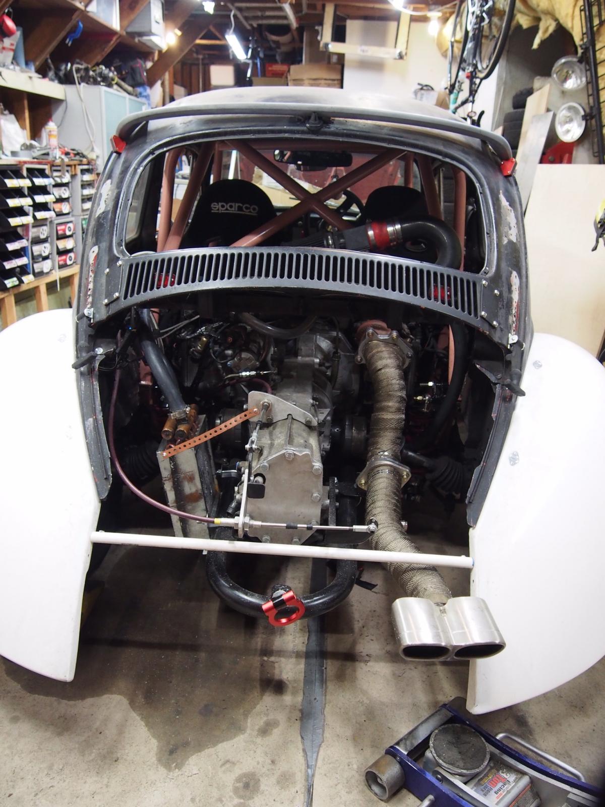
Since I can’t make it to any car shows, I figure I’d show it off on the interwebs.


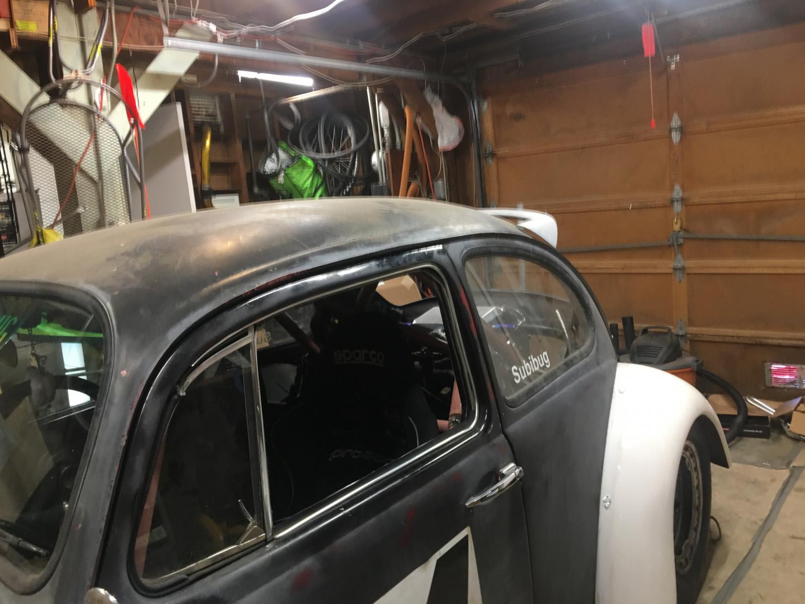
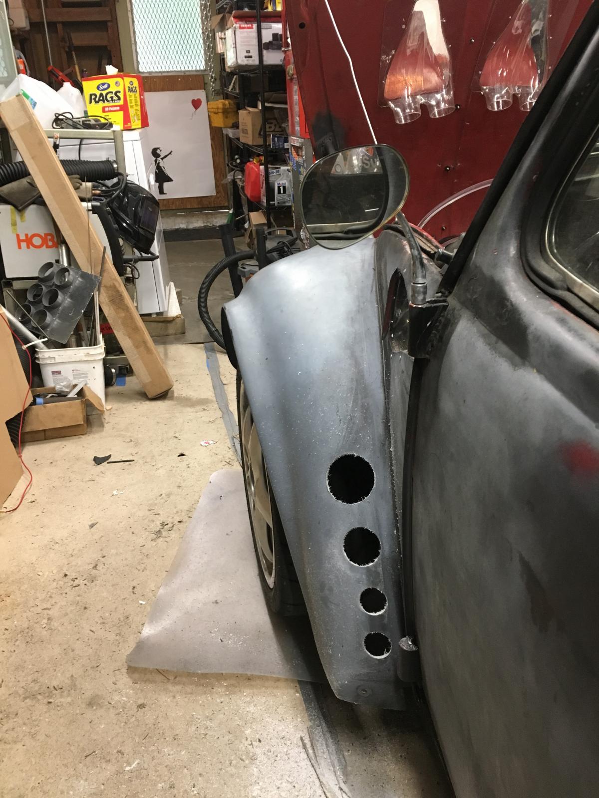


-
maurice
- Posts: 105
- Joined: Sun Apr 03, 2016 10:49 am
Re: Mid engine 66 bug subaru powered
Walk around
https://m.youtube.com/watch?v=Wpywnk6JpcY
Video of my nitrous testing, speedo is off 75mph = 65 actual
https://m.youtube.com/watch?v=9M1sh1x-nMI
https://m.youtube.com/watch?v=Wpywnk6JpcY
Video of my nitrous testing, speedo is off 75mph = 65 actual
https://m.youtube.com/watch?v=9M1sh1x-nMI
-
maurice
- Posts: 105
- Joined: Sun Apr 03, 2016 10:49 am
- panel
- Posts: 4227
- Joined: Sun Sep 24, 2000 12:01 am
Re: Mid engine 66 bug subaru powered
Nice with the ear protection on !
'65 Bus with a JDM Subaru EJ20 Turbo
Built by Germans powered by Japanese and brought together by Canadians
Built by Germans powered by Japanese and brought together by Canadians
- panel
- Posts: 4227
- Joined: Sun Sep 24, 2000 12:01 am
Re: Mid engine 66 bug subaru powered
Can't remember if you told us but where did you get the shifting device/mount and cables etc ?
'65 Bus with a JDM Subaru EJ20 Turbo
Built by Germans powered by Japanese and brought together by Canadians
Built by Germans powered by Japanese and brought together by Canadians
-
maurice
- Posts: 105
- Joined: Sun Apr 03, 2016 10:49 am
Re: Mid engine 66 bug subaru powered
Shifter is from an rsx I got in the junk yard. Mr2’s and all Honda Accord’s (manual of course) use cable shifters.
The cables are push pull ones I got from Kartek off road, I got the 3” travel ones, but they actually caused me some issues mounting them onto my shifter, and I really should have gone with 2” cables. The rest of the linkage and brackets I made myself.
The cables are push pull ones I got from Kartek off road, I got the 3” travel ones, but they actually caused me some issues mounting them onto my shifter, and I really should have gone with 2” cables. The rest of the linkage and brackets I made myself.
-
maurice
- Posts: 105
- Joined: Sun Apr 03, 2016 10:49 am
Re: Mid engine 66 bug subaru powered
It had a couple really minor issues after those doughnuts. And after another few hundred miles, ended up being a couple spun rods. I totally oil starved.
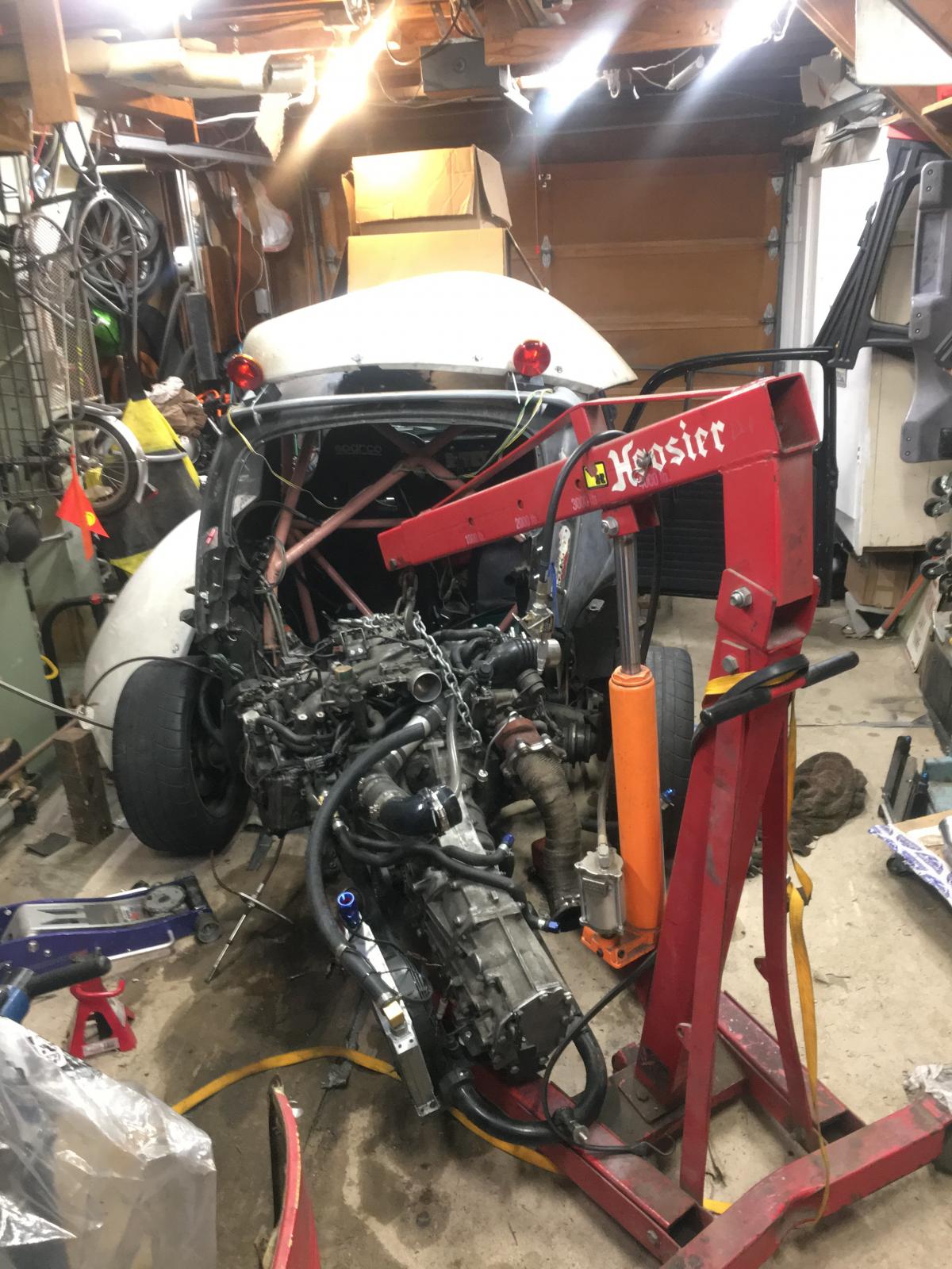
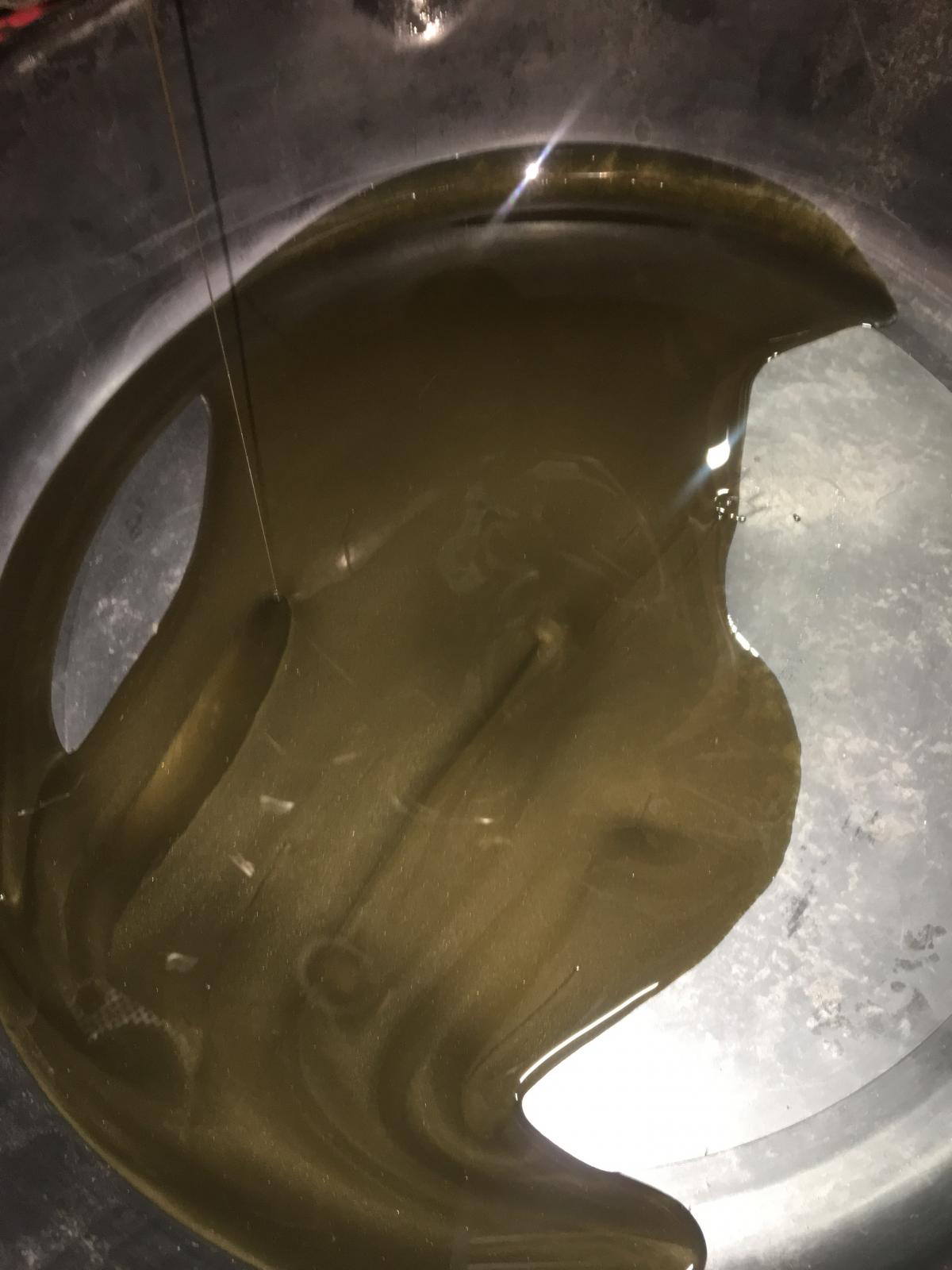
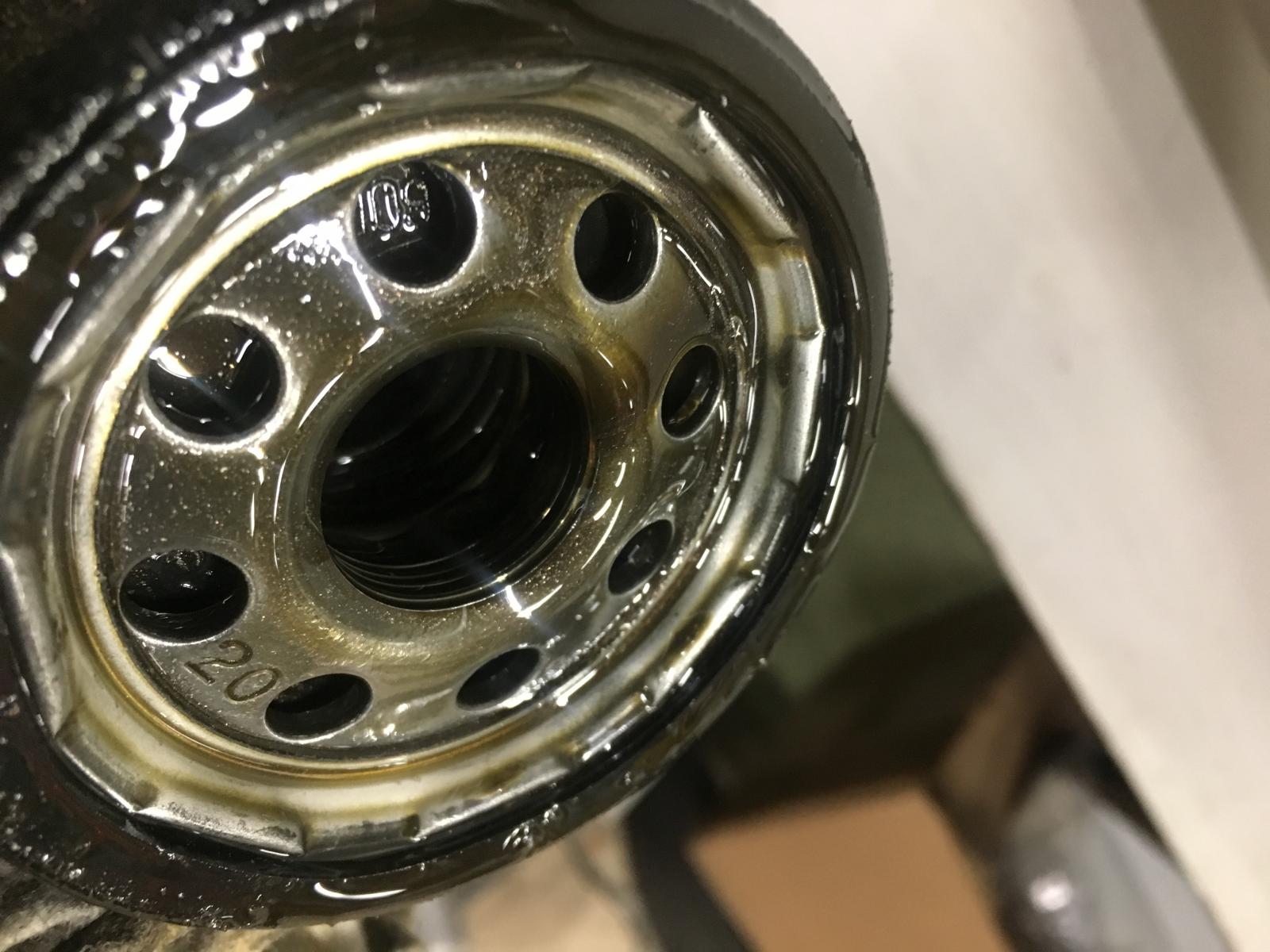
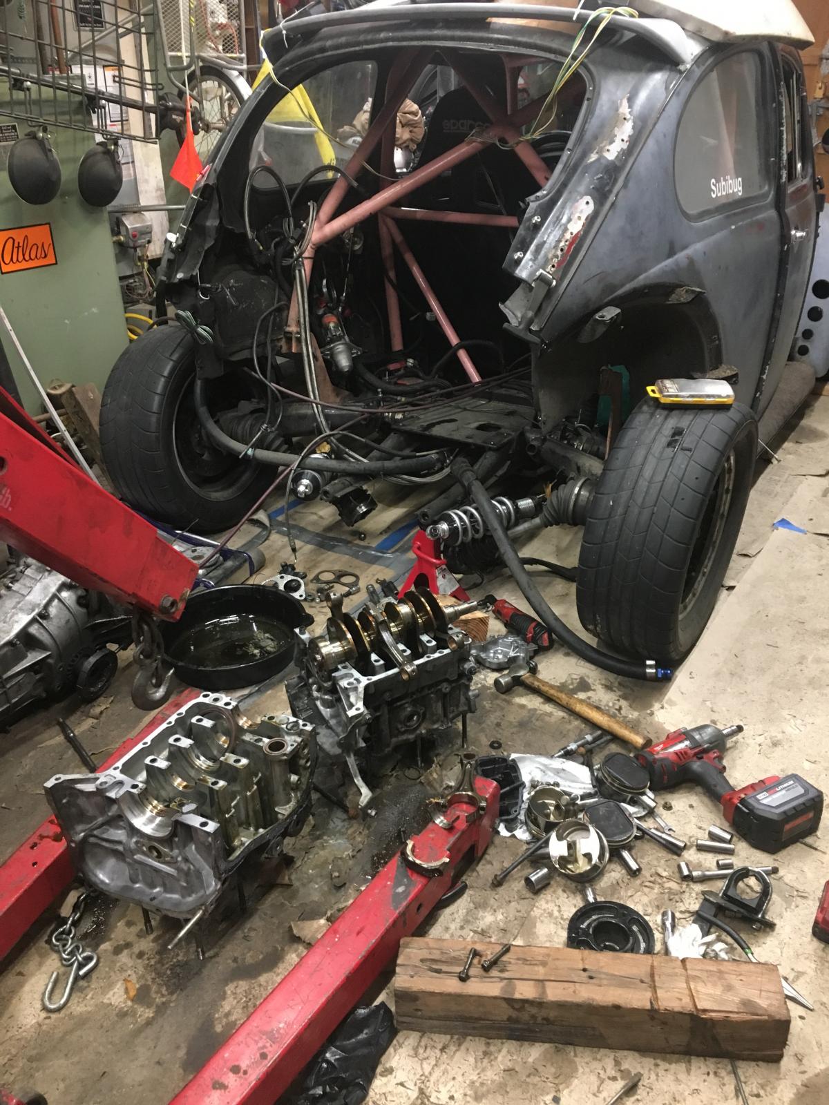
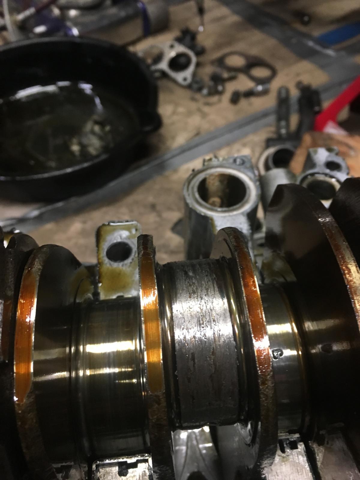
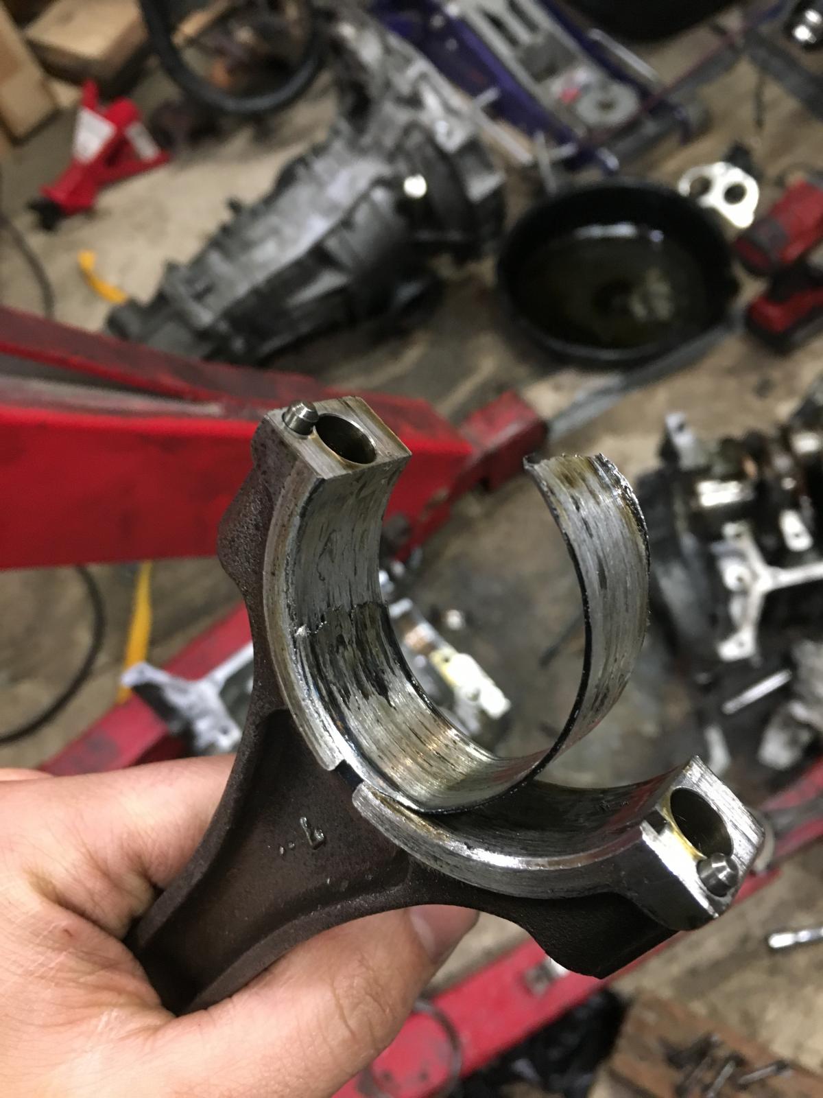
I’ll rebuild this one again with a killer b setup. And keep building my next engine too


I’ll rebuild this one again with a killer b setup. And keep building my next engine too